Acoustic mechanical retainer

a mechanical retainer and liner technology, applied in the direction of machines/engines, air-flow influencers, instruments, etc., can solve problems such as expansion and contraction, and achieve the effect of improving noise attenuation performan

Active Publication Date: 2007-11-20
RTX CORP
View PDF19 Cites 22 Cited by
  • Summary
  • Abstract
  • Description
  • Claims
  • Application Information

AI Technical Summary

Benefits of technology

[0006]An example liner assembly according to this invention includes an acoustically active retainer for covering a seam in a face sheet for improving noise attenuation performance.
[0008]The face sheet is formed from one or several individual sheets with edges adjacent each other that form a seam. The seam results from assembly tolerance stack-ups and also provides for limited expansion and contraction during operation. The seam is covered by a retainer to protect the edges of the face sheet and the underlying noise attenuation layer from damage. The retainer is bonded to the face sheet over the seam and includes a second plurality of holes that communicates noise energy through the retainer to the noise attenuation layer. Communication of noise energy through the retainer provides an acoustically active seam that aids in the dissipation of noise energy and thereby reduces the level of sound emitted from the duct.
[0009]Accordingly, the example retainer of this invention provides an acoustically active mechanical retainer that includes a plurality of openings to communicate noise energy to a noise attenuation layer that improves noise attenuation properties of the liner assembly.

Problems solved by technology

The seam results from assembly tolerance stack-ups and also provides for limited expansion and contraction during operation.

Method used


Image

  • Acoustic mechanical retainer
  • Acoustic mechanical retainer
  • Acoustic mechanical retainer

Examples


Embodiment Construction

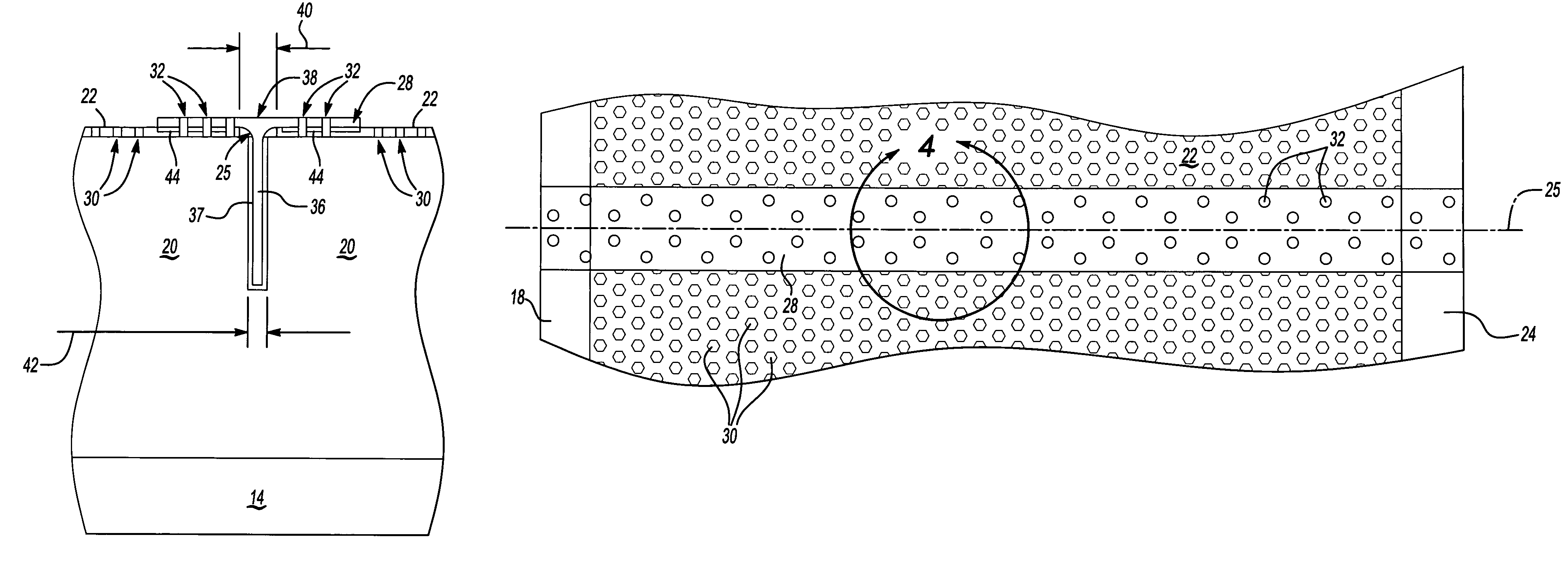
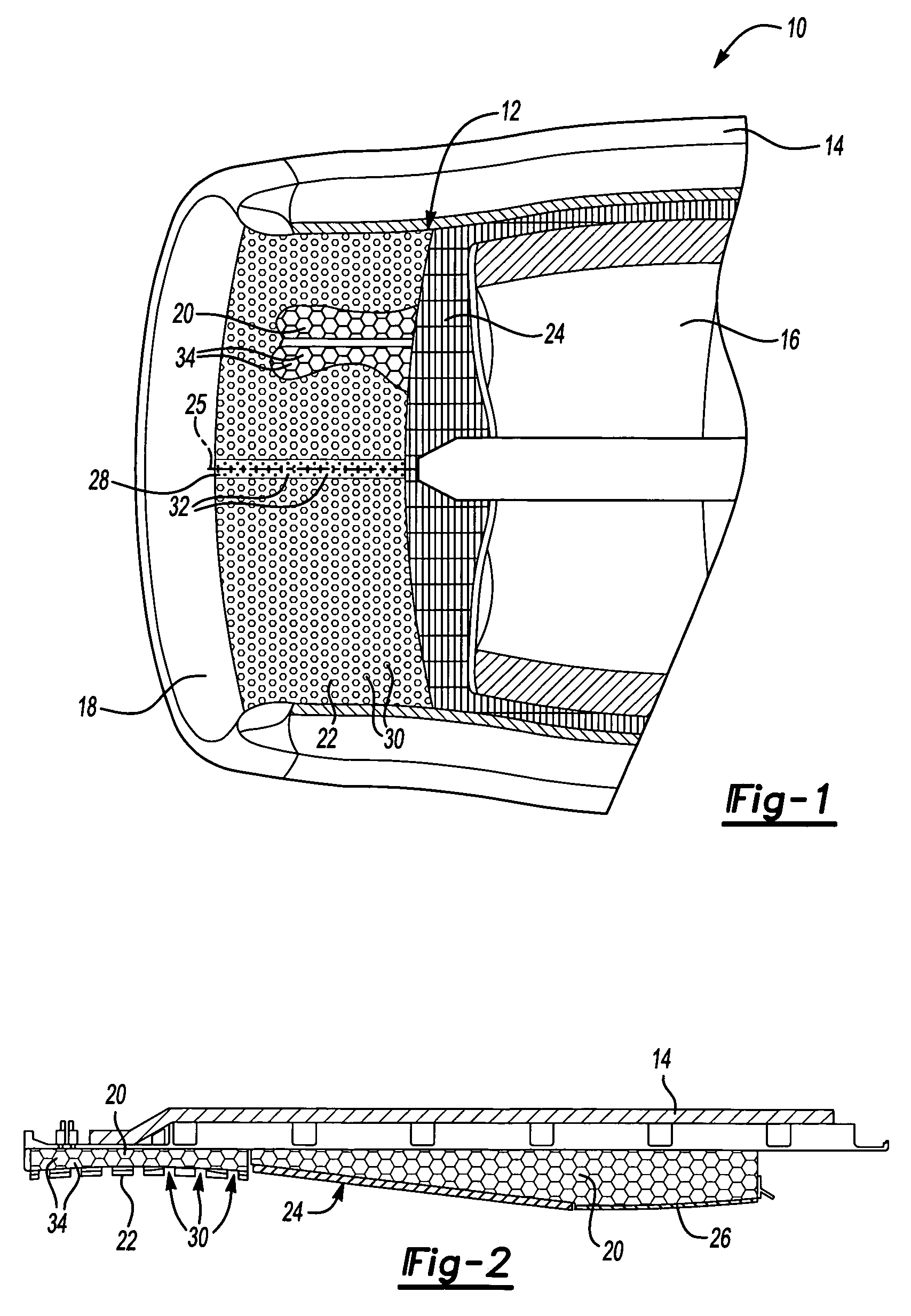
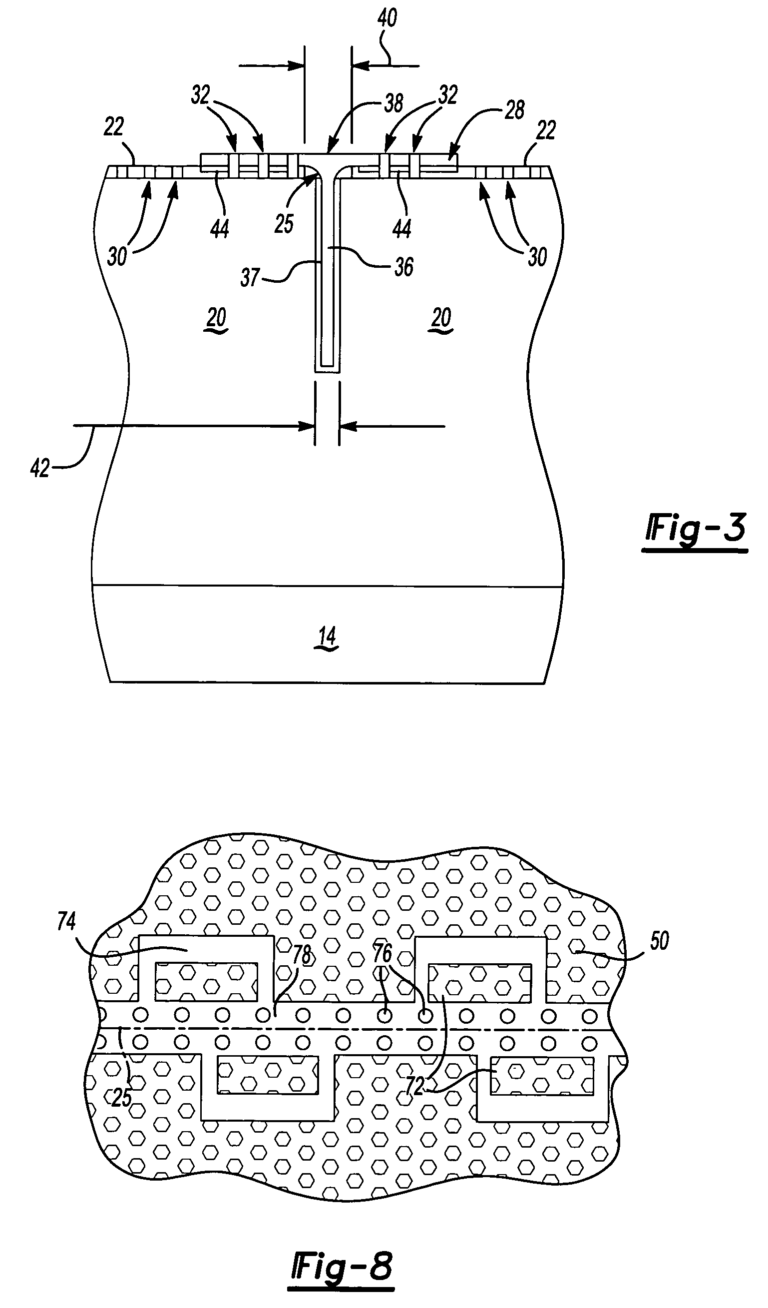
[0019]Referring to FIGS. 1 and 2, a duct commonly known as a fan case assembly 10 for a turbine engine includes a liner assembly 12 mounted within a housing 14. A cowling 18 defines a leading edge of the fan case assembly 10 and is flush with an interior surface of the liner assembly 12. The liner assembly 12 includes a noise attenuation layer 20 that is covered by a face sheet 22. Rearward of the face sheet 22, the noise attenuation layer 20 is covered by an abradable strip 24 that is adjacent a fan blade 16. The abradable strip 24 includes a structure and material that can endure limited contact with the fan blade 16 to protect both the fan blade 16 and the fan case assembly 10. Rearward of the abradable strip 24 is a plate 26. The plate 26 protects the fan case assembly 10 against possible impacts from debris. Although this invention is described and shown by example as a fan case liner, any duct including noise attenuation features would benefit from this disclosure and is withi...


PUM


Abstract

A fan case assembly includes a noise attenuation layer that is covered by a face sheet. The face sheet includes a first plurality of openings. The noise attenuation layer includes a plurality of individual cells that are in communication with at least one of the first plurality of openings. Noise energy is communicated through the first plurality of openings into the individual cells and dissipated to reduce noise emissions. A seam in the face sheet is covered to protect the underlying noise attenuation layer from damage by a retainer. The retainer is bonded to the face sheet over the seam and includes a second plurality of holes that communicates noise energy through the retainer to the noise attenuation layer. Communication of noise energy through the retainer provides an acoustically active seam that aids in the dissipation of noise energy and thereby reduces the level of sound emitted from the engine.

Description

BACKGROUND OF THE INVENTION[0001]This invention generally relates to a liner assembly for a duct, and more particularly to a liner assembly including an acoustically active retainer.[0002]Conventional turbine and turbofan engines for aircraft include a plurality of fan blades that rotate within a duct commonly known as a fan case. The fan case serves as a protective covering to protect the fan blades and the aircraft. Further the fan case channels airflow into the turbine engine. The inner surface of the fan case is constructed to withstand impacts from objects that may come into contact with the fan case and includes acoustical features to reduce noise emitted from the engine.[0003]The acoustical features include a layer of noise attenuation structures covered by a protective face layer including a plurality of openings. The face layer is typically a thin sheet of metal or composite material mounted over the noise attenuation structure. Noise causing pressure disturbances emanate t...

Claims


Application Information

Patent Timeline
Patent Type & Authority Patents(United States)
IPC IPC(8): B64C1/40B64C1/12B64C1/06B64D33/02F02K1/82F02K99/00
CPCF02C7/045F02K1/827F05D2250/283Y02T50/672Y02T50/60
Inventor SANICKI, SCOTTCOSTA, MARK W.
Owner RTX CORP
Why Eureka
Try Eureka