Electronic vital relay

a vital relay and electronic technology, applied in the direction of railway signalling, vehicle route interaction devices, railway signalling and safety, etc., can solve the problems of affecting safety or reliable operation, requiring considerable preventive maintenance, and preventing accurate detection

Active Publication Date: 2007-11-20
ANSALDO STS USA INC
View PDF21 Cites 16 Cited by
  • Summary
  • Abstract
  • Description
  • Claims
  • Application Information

AI Technical Summary

Problems solved by technology

The relay will drop out of an operated condition if a train or a broken rail is in the particular track section being controlled or if there is otherwise a fault on the system which prevents an accurate detection of the presence of a train.
The problem with vane relays is that, as an electromechanical device with moving parts, they require considerable preventive maintenance to assure reliable operation.
If local voltage regulation is poor, safety or reliable operation can be impacted.
This increases the risk of the track relay's failure to drop in the presence of a broken rail.

Method used


Image

  • Electronic vital relay
  • Electronic vital relay
  • Electronic vital relay

Examples


Embodiment Construction

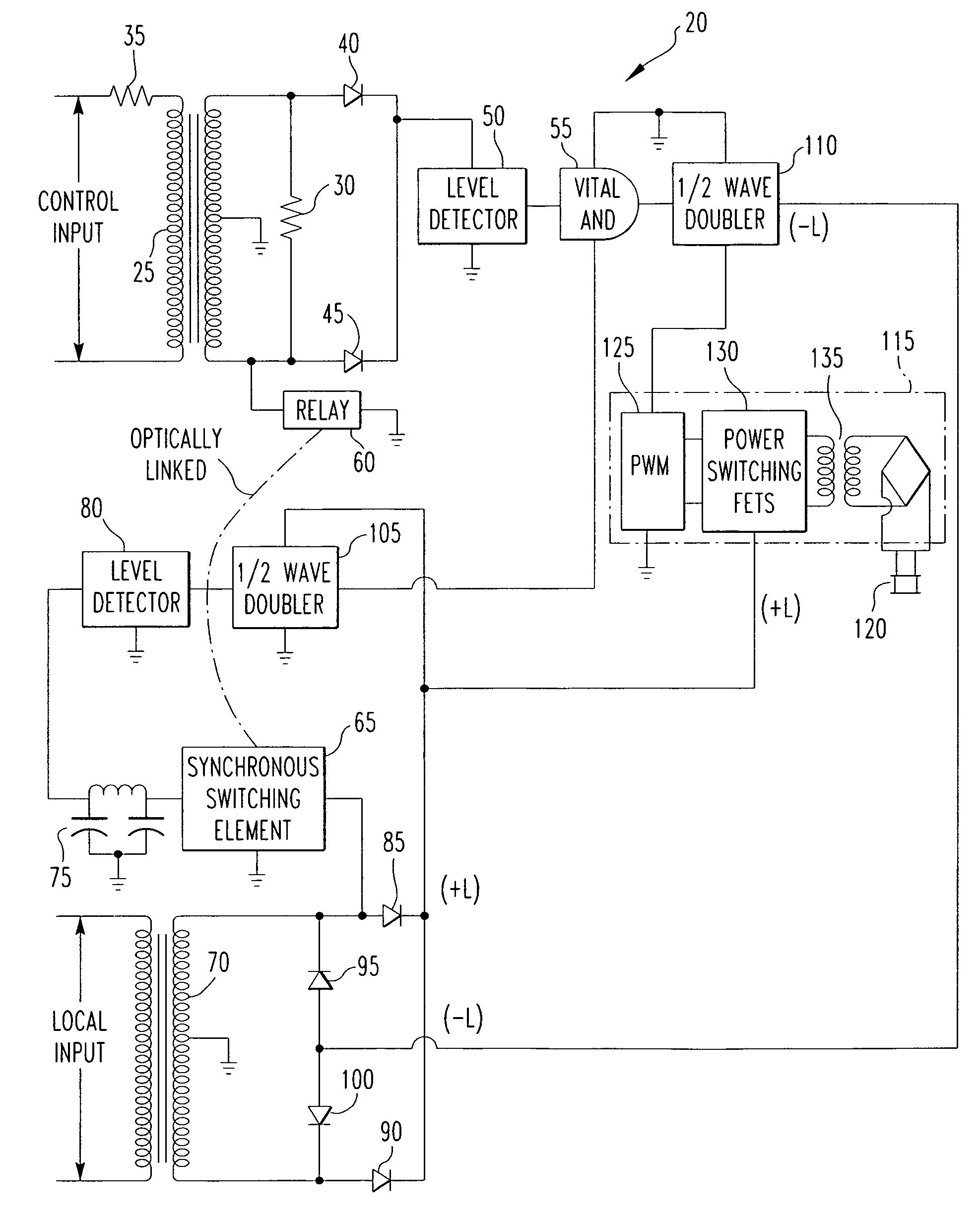
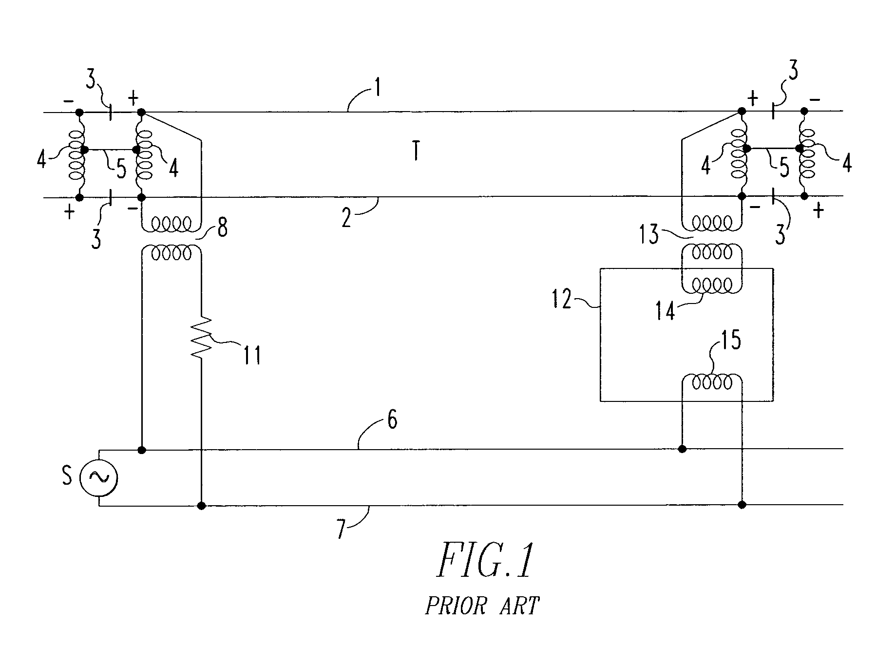
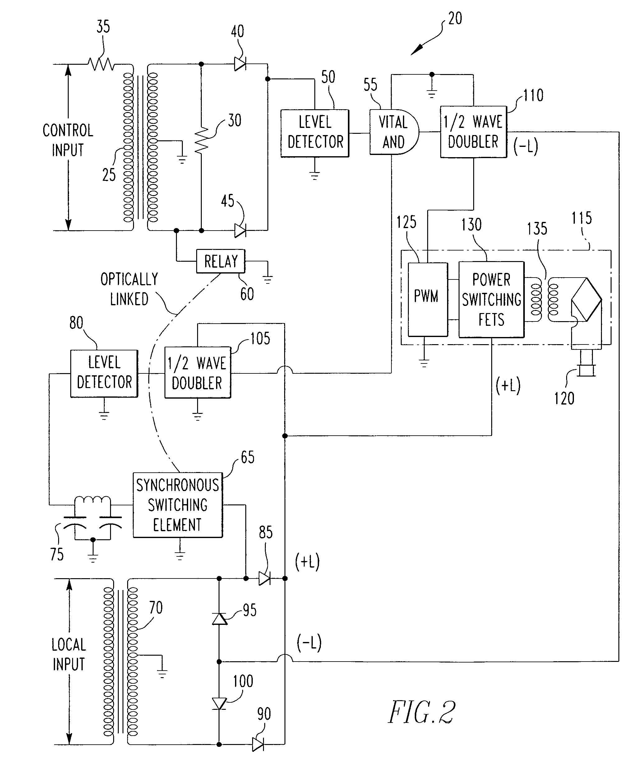
[0017]FIG. 2 is a schematic diagram of an electronic vane relay architecture 20 according to the present invention. The electronic vane relay architecture 20 may be used in connection with the track configuration shown in FIG. 1, wherein it is the vital relay circuit 12. As described above, a prior art electromechanical vane relay operates by producing torque that drives mechanically linked metallic contacts wherein the torque is proportional to the product of: (i) the current in the local winding, (ii) the current in the control / track winding, and (iii) the cosine of the angular difference of those currents. The current portion of the product is an indication of whether a train or a broken rail is present in the track section being monitored, and the phase portion of the product is an indication of whether a fault condition exists between track sections. In contrast, in electronic vane relay architecture 20, the determination of sufficient current and phase difference for operation...


PUM


Abstract

A railroad signaling method includes measuring a track current on a first track section, measuring a local voltage on the railroad line wires, determining whether a magnitude of the track current meets or exceeds a threshold value independent of the local voltage, and determining whether the track current and the local voltage are nominally in phase with one another in a manner that is independent of the track current measuring step. A first signal is provided only if the magnitude is determined to meet or exceed the threshold and the track current and local voltage are determined to be nominally in phase. The first signal is an indication that a train is not present in the track section, that the track section does not have a broken rail, and that the insulated joints that bound the track section do not include a fault condition. An associated relay arrangement is also provided.

Description

BACKGROUND OF THE INVENTION[0001]1. Field of the Invention[0002]The present invention relates to signaling system for railroads, and in particular to an electronic vital relay used to detect the presence of a train or a broken rail in particular track sections and / or track fault conditions between track sections.[0003]2. Description of the Prior Art[0004]Railroad systems, such as electrified railroad systems that employ power frequently track circuits, utilize signaling systems to provide signals for train operators and to control the operation of railroad crossing gates and warning lights. In such systems, each track circuit is bounded by insulated joints so that the presence of a train can be defined to a unique section of track. Railroad signaling systems use what is termed a vital relay or track relay to detect the presence of a train or a broken rail in particular track sections and / or track fault conditions between track sections (i.e., a fault in the insulated joint connectin...

Claims


Application Information

Patent Timeline
Patent Type & Authority Patents(United States)
IPC IPC(8): B61L21/00
CPCB61L1/185
Inventor FRANKE, RAYMOND C.
Owner ANSALDO STS USA INC
Why Eureka
Try Eureka