
Solar battery module, installation structure for solar battery module, roof with power generating function of the installation structure, and method of installing solar battery module

a technology of solar cells and solar cells, applied in the direction of climate sustainability, electric vehicles, constructions, etc., can solve the problems of large amount of rainwater invading, work takes considerable time, and the waterproof condition is sometimes impaired

Inactive Publication Date: 2007-11-20
KANEKA CORP
View PDF10 Cites 66 Cited by
  • Summary
  • Abstract
  • Description
  • Claims
  • Application Information

AI Technical Summary

Benefits of technology

[0009]A solar battery module provided according to the invention is a single solar battery module comprising a solar battery constituting a roofing member and a supporting stand provided on the eaves-side end of the back face of this solar battery module and whereby this solar battery is fixed to the main roof structure, a plurality of these being disposed in mutually adjacent fashion on the main roof structure, in which: a mounting groove that receives the ridge-side end of a solar battery of a solar battery module that is adjacently disposed on the eaves side is formed in said supporting stand and a recessed part that extends along the eaves side from the ridge side is formed in one left or right side end of the solar battery module, a projecting part of a shape that will enter said recessed part is formed on the other side end of a solar battery module and waterproofing means is provided that, in a condition in which said projecting part is inserted into a corresponding recessed part of an adjacently disposed solar battery module at the side, prevents circulation of rainwater invading to the upper surface of this projecting part to the lower surface.

Problems solved by technology

However, if roof panels were installed providing sealing members between the ends of adjacent solar battery modules in this way, not only did this work take considerable time but also the waterproof condition was sometimes impaired at an early date owing to deterioration of the sealing members.
Under severe conditions of wind and rain, there is therefore the possibility of large amounts of rainwater invading from the gaps or damaged portions of the sealing; such rainwater invasion causes various problems at the back face of the solar battery modules.
For example, accumulation of rainwater over a long period on the main roof structure may cause leakage of water into the building at this location or leakage of electricity and / or accumulated humidity may produce faults of the solar battery modules.

Method used


Image

  • Solar battery module, installation structure for solar battery module, roof with power generating function of the installation structure, and method of installing solar battery module
  • Solar battery module, installation structure for solar battery module, roof with power generating function of the installation structure, and method of installing solar battery module
  • Solar battery module, installation structure for solar battery module, roof with power generating function of the installation structure, and method of installing solar battery module

Examples


Embodiment Construction

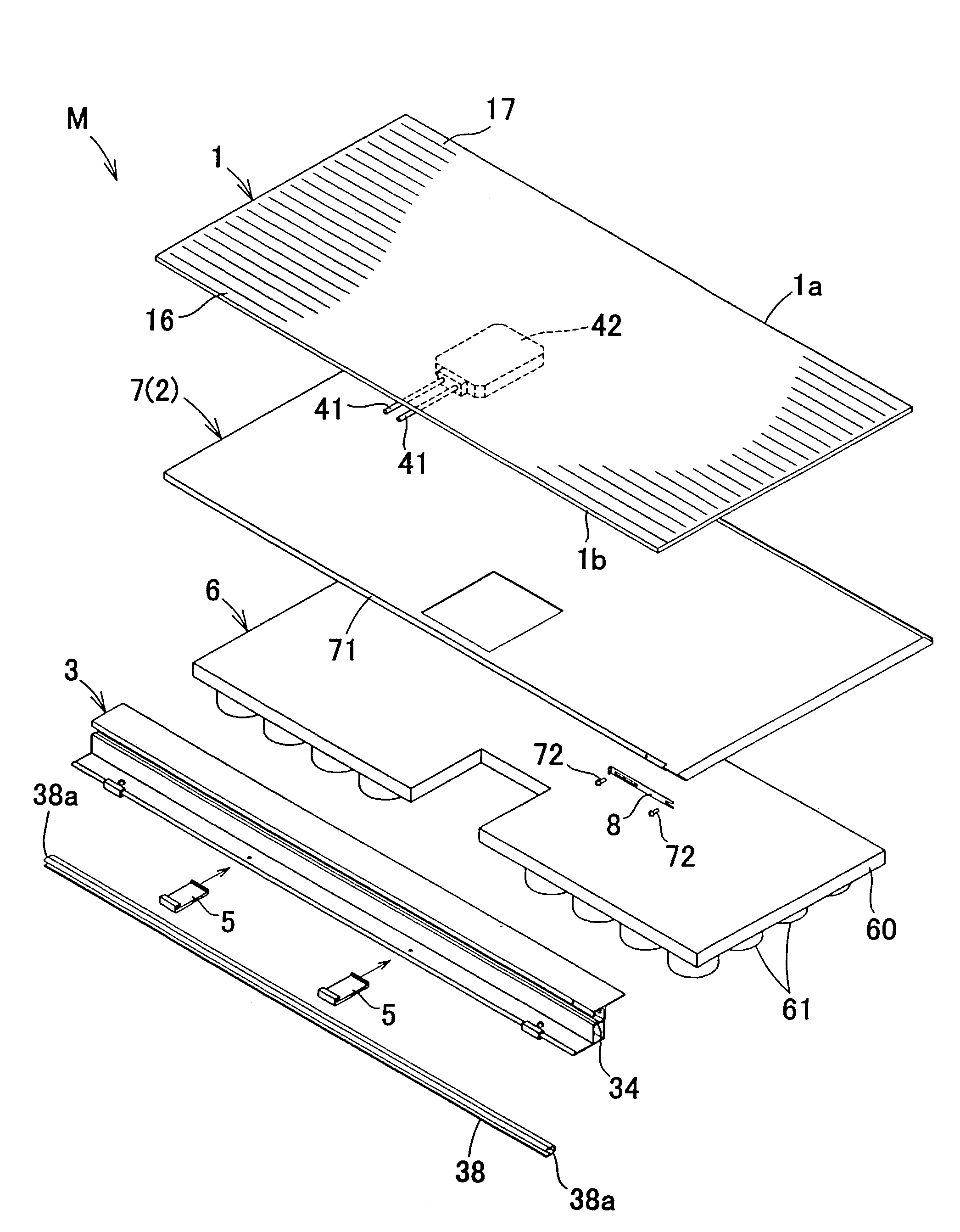
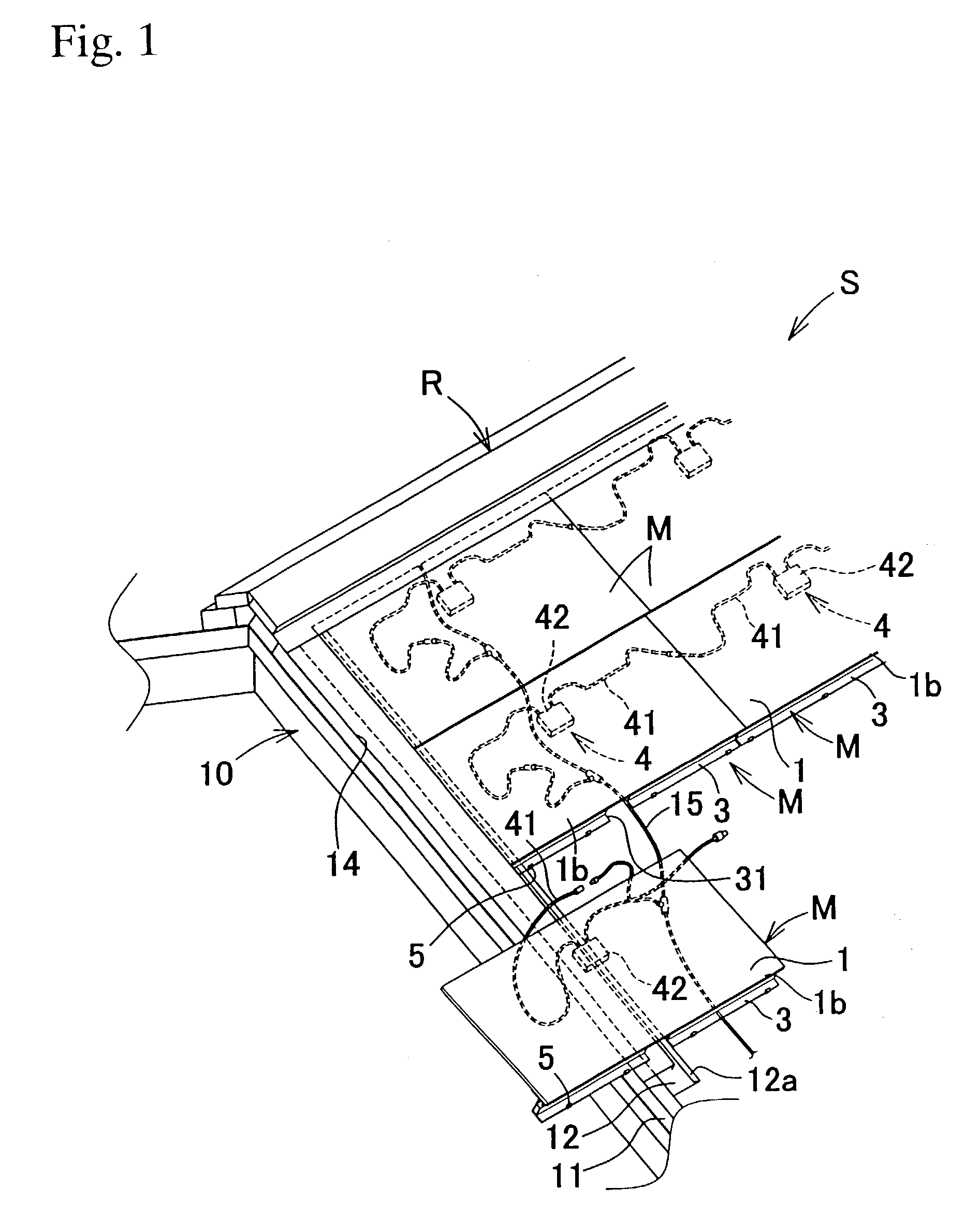
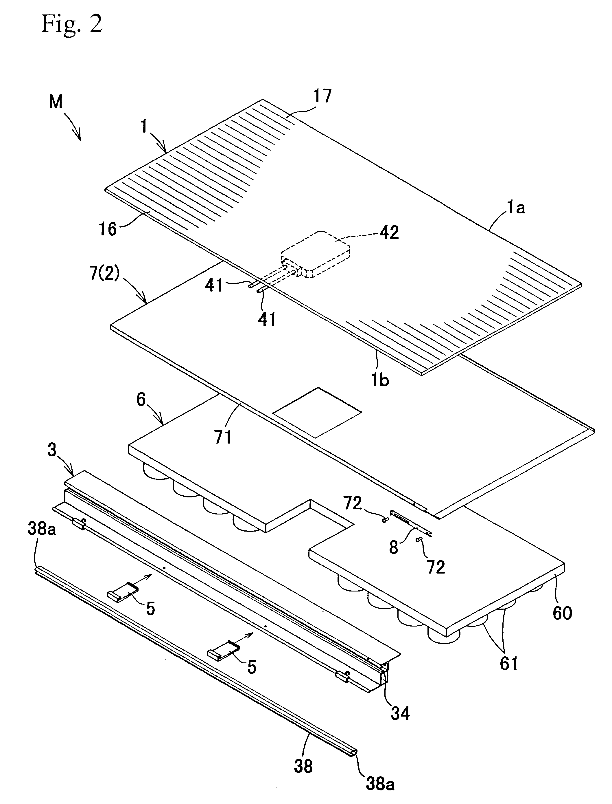
[0065]Next, an embodiment of the present invention is described in detail with reference to the appended drawings. FIG. 1 to FIG. 16 illustrate a typical embodiment of the present invention. In the drawings, reference symbol 1 indicates a solar battery, 2 indicates a mounting member, 3 a supporting stand, M a solar battery module and S the installation structure thereof, respectively.

[0066]As shown in FIG. 1, the solar battery modules M are solar battery modules of the type integral with building material that are capable of being independently directly laid on a main roof structure and comprise a solar battery 1 constituting the roofing material and a supporting stand 3 provided at the eaves side end 1b of the solar battery and whereby the solar battery 1 is fixed on the main roof structure 10.

[0067]These solar battery modules M are used as roof panels; a roof R having a power-generating function is constituted by arranging a plurality of these in mutually adjacent fashion along th...


PUM


Abstract

A solar battery module capable of assuring the fluid-tight structure of the roof panels adjacent to each other in lateral direction, realizing a weathering between the modules, eliminating a process for providing a seal member between the ends of the modules adjacent to each other, and facilitating an assembly operation, wherein a recessed part extending from the ridge side to the eaves side of the solar battery module is formed at lateral one end thereof, a projected part in the shape of coming into the recessed part is formed at the other end, and a waterproof means for suppressing the rain water invaded onto the upper surface of the projected part from circulating to the lower surface thereof is installed on the projected part in the state of being inserted into the corresponding recessed part of the solar battery module disposed adjacently to the side.

Description

TECHNICAL FIELD[0001]The present invention relates to a solar battery module suitable for a solar power-generating system, an installation structure whereby this is disposed on the main structure of a roof, a roof with a power-generating function having such an installation structure and a method of installation whereby a solar battery module is installed on the main structure of a roof.BACKGROUND ART[0002]One known means of obtaining electrical energy is a solar battery module comprising solar cells. Such solar battery modules are frequently disposed in locations where they are easily able to receive solar energy, such as on the roofs of buildings.[0003]Consideration has been given to utilizing solar battery modules themselves as roof panels. In such cases, a roof with a power-generating function is constituted by covering the underlay material of the main structure of the roof of the building with the solar battery modules.[0004]In a solar power-generating system using such solar ...

Claims


Application Information

Patent Timeline
Patent Type & Authority Patents(United States)
IPC IPC(8): H01L31/05E04D3/40H01L31/048H02J7/00
CPCF24J2/4614F24J2/5228F24J2/5243H02S20/23E04D2001/3458Y02B10/12Y02B10/20Y02E10/47F24J2002/4661F24S25/40F24S25/60F24S40/44F24S2025/6002Y02B10/10Y02E10/50
Inventor NOMURA, TAKUJIHATSUKAIWA, TERUKITOMITA, HIROHIKO
Owner KANEKA CORP
Learn More