Cooling apparatuses and methods employing discrete cold plates compliantly coupled between a common manifold and electronics components of an assembly to be cooled

a technology of cooling apparatus and cold plate, which is applied in the direction of power cables, semiconductor/solid-state device details, cables, etc., can solve the problems of increasing device temperature, power dissipation, and therefore heat production, and achieve good thermal interface

Active Publication Date: 2007-11-20
LENOVO GLOBAL TECH INT LTD
View PDF22 Cites 71 Cited by
  • Summary
  • Abstract
  • Description
  • Claims
  • Application Information

AI Technical Summary

Problems solved by technology

Failure to remove the heat thus produced results in increased device temperatures, potentially leading to thermal runaway conditions.
First, power dissipation, and therefore heat production, increases as device operating frequencies increase.
Further, as more and more devices are packed onto a single chip, power density (Watts / cm2) increases, resulting in the need to remove more heat from a given size chip or module.
A problem with this configuration is the increase in heat flux at the electronics drawer level.
The above-noted trends have combined to create applications where it is no longer desirable to remove heat from modern devices solely by traditional air cooling methods, such as by using traditional air cooled heat sinks.
In particular, liquids such as refrigerants or other dielectric fluids (e.g., fluorocarbon fluid) exhibit relatively poor thermal conductivity and specific heat properties, i.e., when compared to liquids such as water or other aqueous fluids.
Water-based coolants, however, must be kept from physical contact with electronics components and interconnects, since corrosion and electrical short circuit problems are likely to result from contact.

Method used


Image

  • Cooling apparatuses and methods employing discrete cold plates compliantly coupled between a common manifold and electronics components of an assembly to be cooled
  • Cooling apparatuses and methods employing discrete cold plates compliantly coupled between a common manifold and electronics components of an assembly to be cooled
  • Cooling apparatuses and methods employing discrete cold plates compliantly coupled between a common manifold and electronics components of an assembly to be cooled

Examples


Embodiment Construction

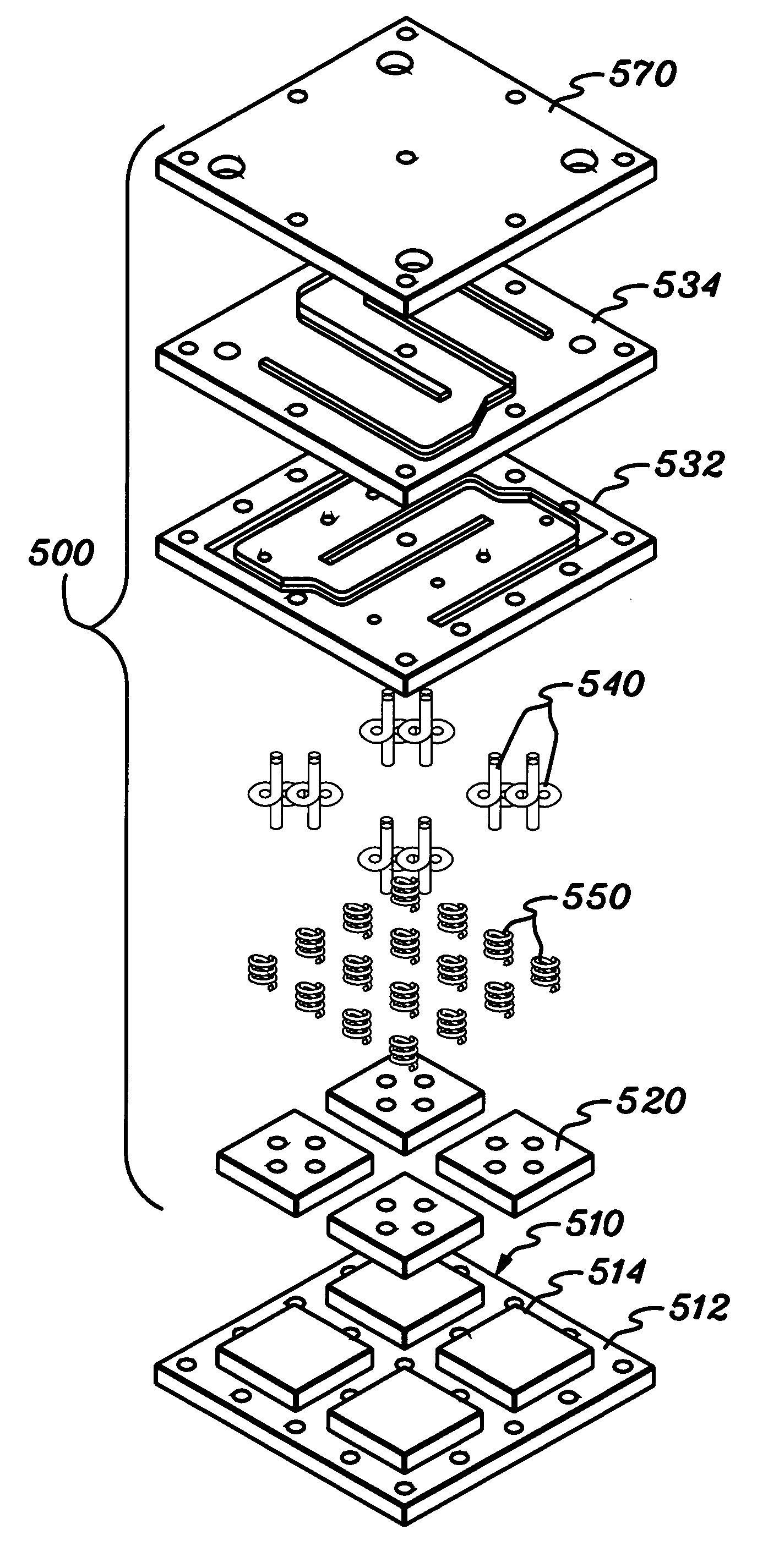
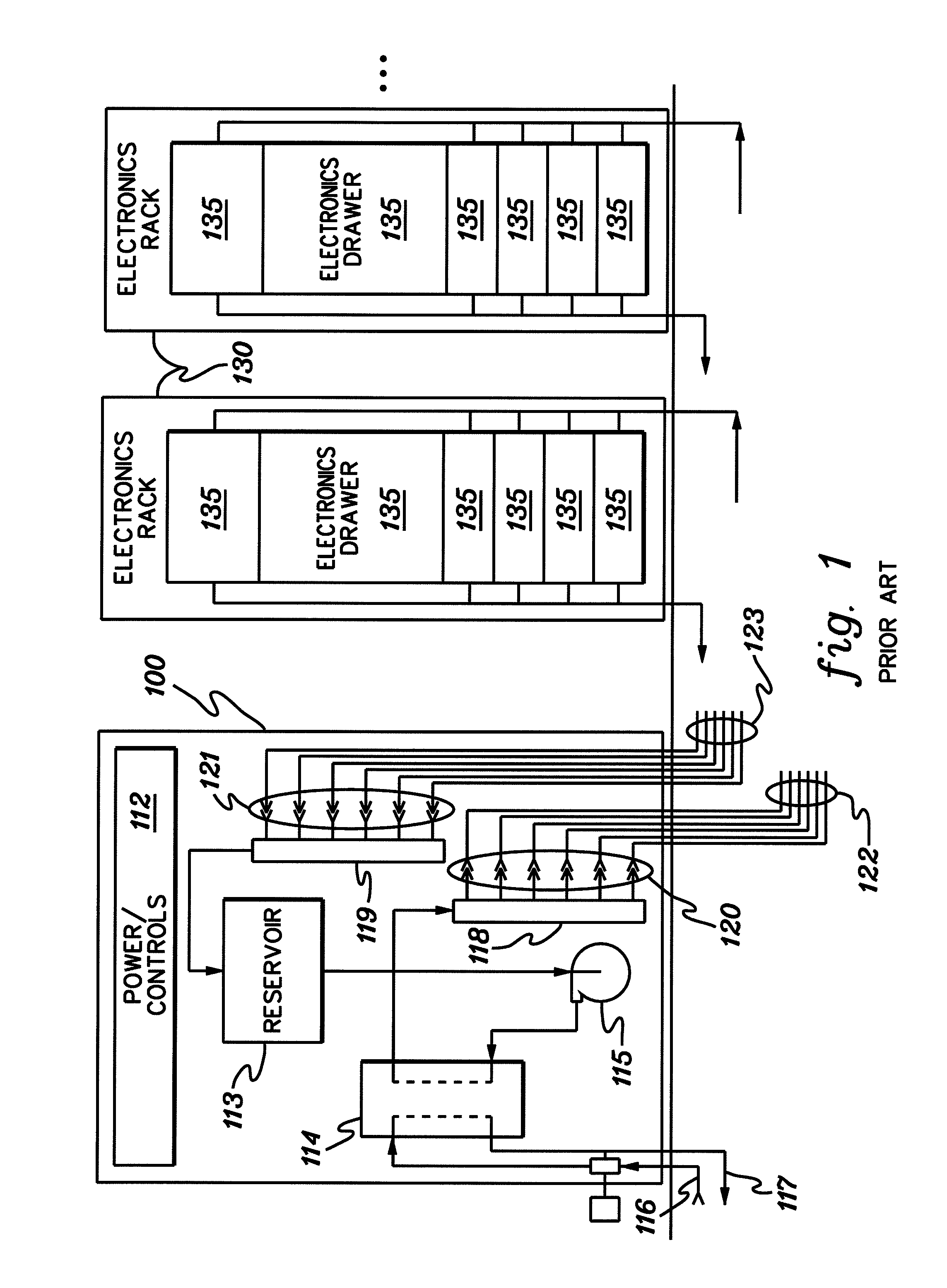
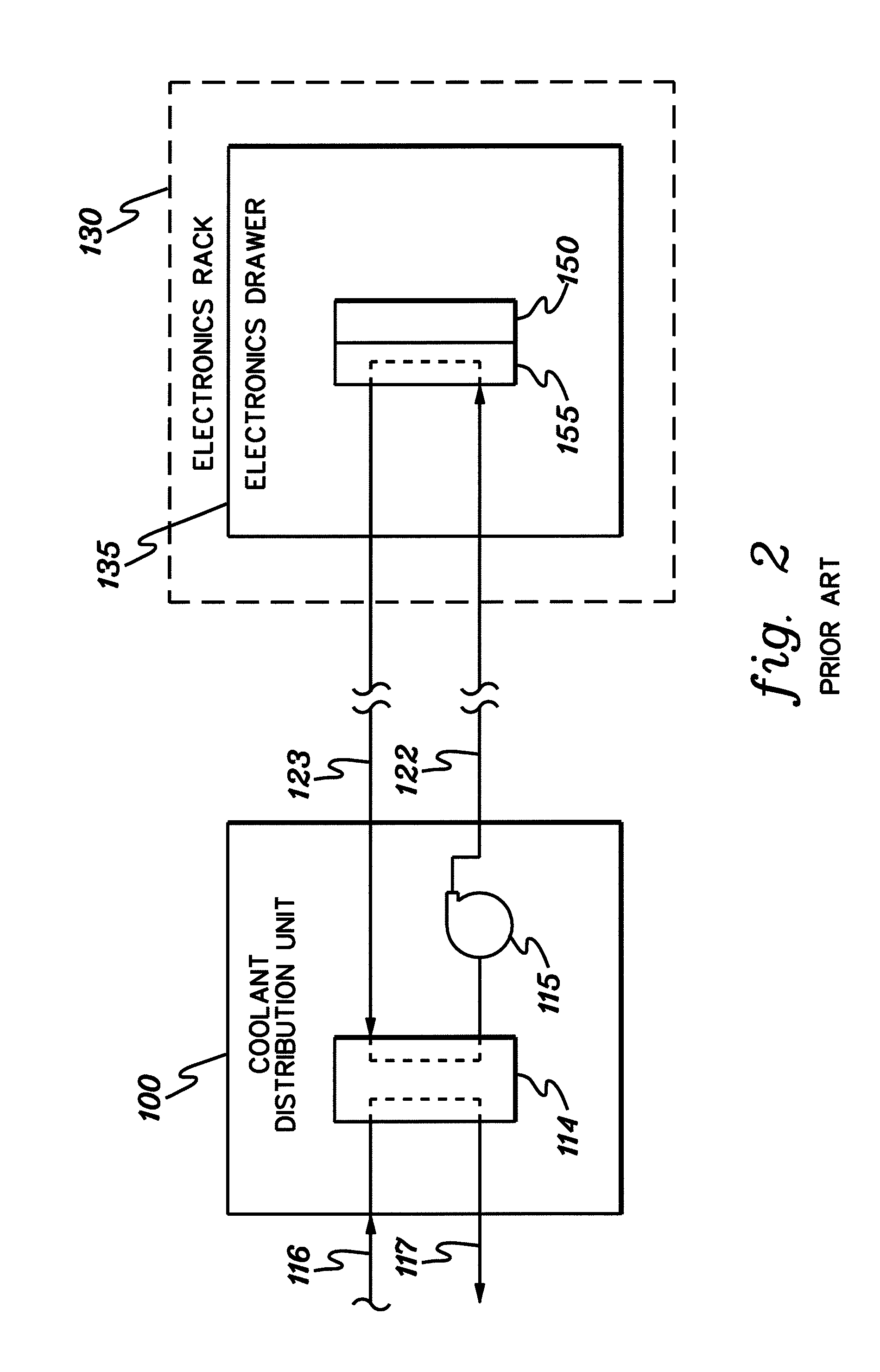
[0031]As used herein, “electronics subsystem” comprises any housing, compartment, drawer, blade, etc., containing one or more heat generating components of a computer system or other electronics system requiring cooling. The term “electronics rack” includes any frame, rack, blade server system, etc., having a heat generating component of a computer system or electronics system, and may be, for example, a stand alone computer processor having high, mid or low end processing capability. In one embodiment, an electronics rack may comprise multiple electronics subsystems, each having one or more heat generating electronics components requiring cooling.

[0032]Each “heat generating electronics component” may comprise a multichip electronics module, a single-chip electronics module, one or more unpackaged integrated circuit die, etc. A “support structure” for the electronics assembly is in one embodiment a substantially planar structure, which may comprise a board, a stiffener, a substrate,...


PUM


Abstract

Cooling apparatuses and methods are provided for cooling an assembly including a planar support structure supporting multiple electronics components. The cooling apparatus includes: multiple discrete cold plates, each having a coolant inlet, coolant outlet and at least one coolant carrying channel disposed therebetween; and a manifold for distributing coolant to and exhausting coolant from the cold plates. The cooling apparatus also includes multiple flexible hoses connecting the coolant inlets of the cold plates to the manifold, as well as the coolant outlets to the manifold, with each hose segment being disposed between a respective cold plate and the manifold. A biasing mechanism biases the cold plates away from the manifold and towards the electronics components, and at least one fastener secures the manifold to the support structure, compressing the biasing mechanism, and thereby forcing the parallel coupled cold plates towards their respective electronics components to ensure good thermal interface.

Description

CROSS-REFERENCE TO RELATED APPLICATIONS[0001]This application contains subject matter which is related to the subject matter of the following applications, which are assigned to the same assignee as this application and which are hereby incorporated herein by reference in their entirety:[0002]“Cooling System and Method Employing a Closed Loop Coolant Path and Micro-Scaled Cooling Structure within an Electronics Subsystem of an Electronics Rack”, Campbell et al., Ser. No. 11 / 008,771, filed Dec. 9, 2004; and[0003]“Cooling Apparatus and Method Employing Discrete Cold Plates Disposed Between a Module Enclosure and Electronics Components to be Cooled,” Campbell et al., Ser. No. 11 / 258,314, filed Oct. 10, 2005.TECHNICAL FIELD[0004]The present invention relates to cooling apparatuses and methods for removing heat generated by electronics components (e.g., devices, modules, systems, etc.) and to methods of constructing such cooling apparatuses. More particularly, the present invention relat...

Claims


Application Information

Patent Timeline
Patent Type & Authority Patents(United States)
IPC IPC(8): H05K7/20F28F7/00H01L23/34
CPCG06F1/20H05K7/2079G06F2200/201
Inventor CAMPBELL, LEVI A.CHU, RICHARD C.ELLSWORTH, JR., MICHAEL J.IYENGAR, MADHUSUDAN K.SCHMIDT, ROGER R.SIMONS, ROBERT E.
Owner LENOVO GLOBAL TECH INT LTD
Why Eureka
Try Eureka