Manipulatable model for communicating manufacturing issues of a custom part

a technology of custom parts and models, applied in the field of manipulable models, can solve the problems of difficult customer understanding where on a part a particular problem or need to be changed, complex communication between moldmakers and customers, and complex decisions, so as to improve the quality of parts, reduce injection molding costs, and understand the

Active Publication Date: 2007-11-20
PROTOLABS INC
View PDF5 Cites 52 Cited by
  • Summary
  • Abstract
  • Description
  • Claims
  • Application Information

AI Technical Summary

Benefits of technology

[0006]The present invention is a software method and system for communicating manufacturability issues, which is particularly applicable to a customer's part to be injection molded. Rather than communicate solely using fixed images and text, the present invention utilizes motion of a part model in explaining what changes or adjustments should be made to the part to increase part quality, reduce injection molding expenses or make injection molding possible. In one aspect, portions of the part model are highlighted, and a flight pattern is provided which first shows the customer a recognizable orientation of the part and then flies to show the issue location. In another aspect, the part model provided to the customer is user manipulatable such as with a click-drag-drop command of the customer's computer mouse. By adding a moveable aspect to the communication, customers can much better understand which changes are recommended or required of the part.

Problems solved by technology

Historically, moldmaking involves at least one face-to-face meeting between the moldmaker and the customer, with complex communication between the moldmaker and the customer and complex decisions made by the moldmaker regarding the construct of the mold.
While this automation has greatly improved the process of identifying manufacturability issues, communicating those issues to the customer and quoting manufacture of the mold and / or part, problems still remain.
One particular remaining problem is a difficulty of customers in understanding where on a part a particular problem or needed change is located.

Method used


Image

  • Manipulatable model for communicating manufacturing issues of a custom part
  • Manipulatable model for communicating manufacturing issues of a custom part
  • Manipulatable model for communicating manufacturing issues of a custom part

Examples


Embodiment Construction

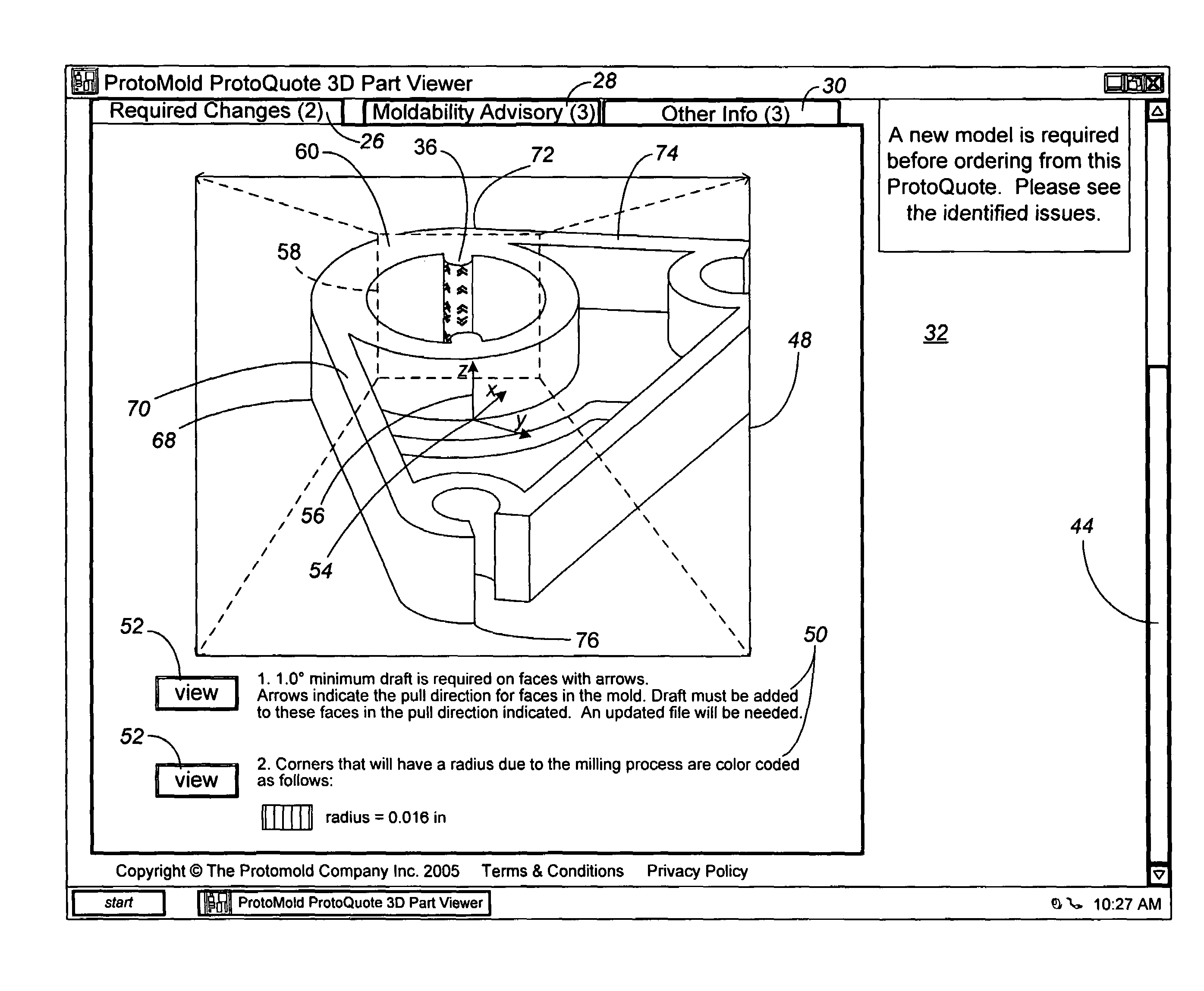
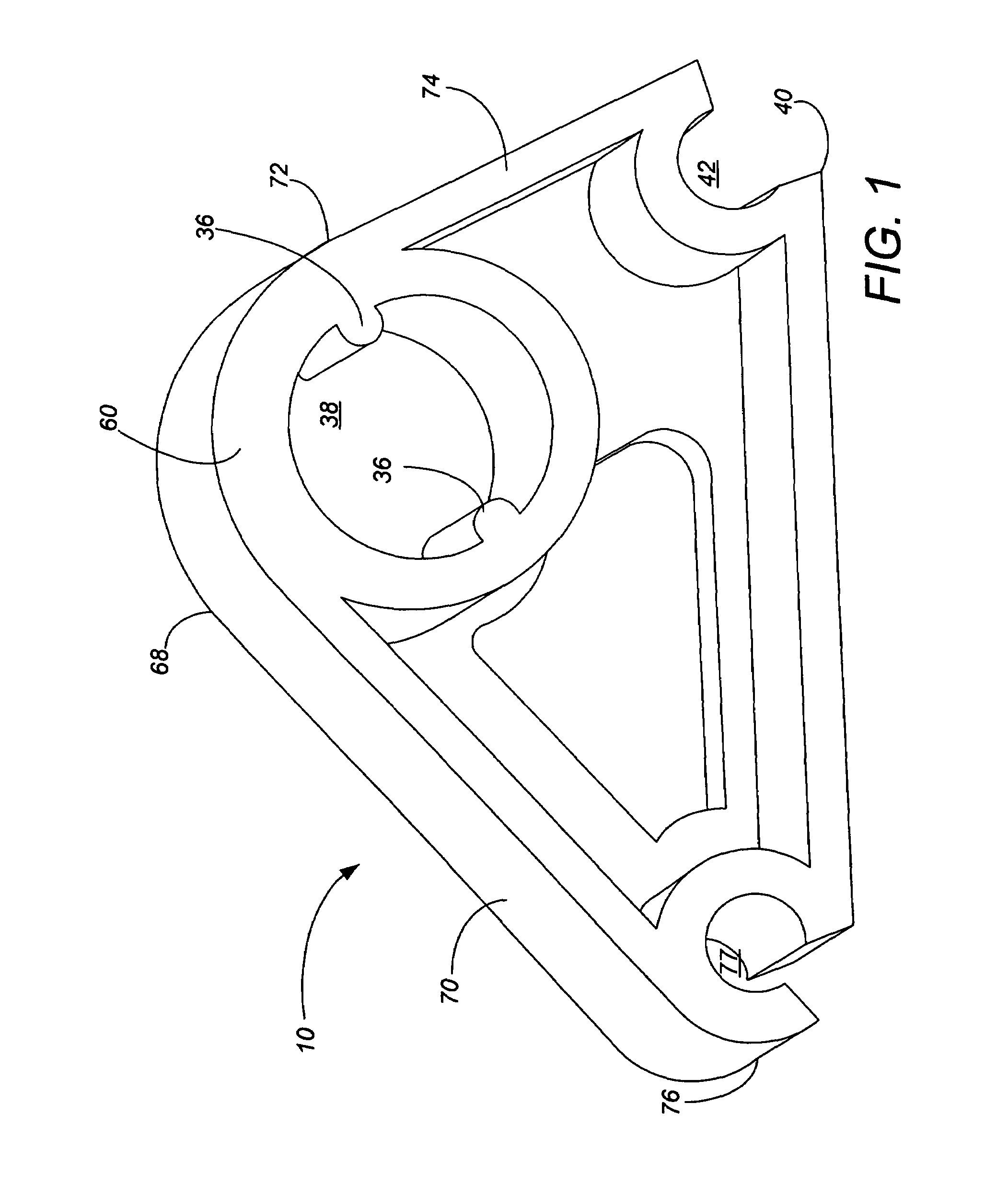
[0012]FIG. 1 shows an exemplary part 10 for discussion purposes of the inventive way to communicate issues associated with the manufacture of that part 10. In this example, the part 10 is a “cam” part custom designed by a customer named John One. In part because the cam 10 is custom-designed (i.e., not a staple article of commerce) by or for this particular customer, the cam 10 includes numerous features, none of which have commonly accepted names. Without commonly accepted names for these features, verbal communication about changes to one or more features of the cam part 10 is difficult. The present invention is particularly contemplated as a better way to communicate changes or injection molding requirements of the part.

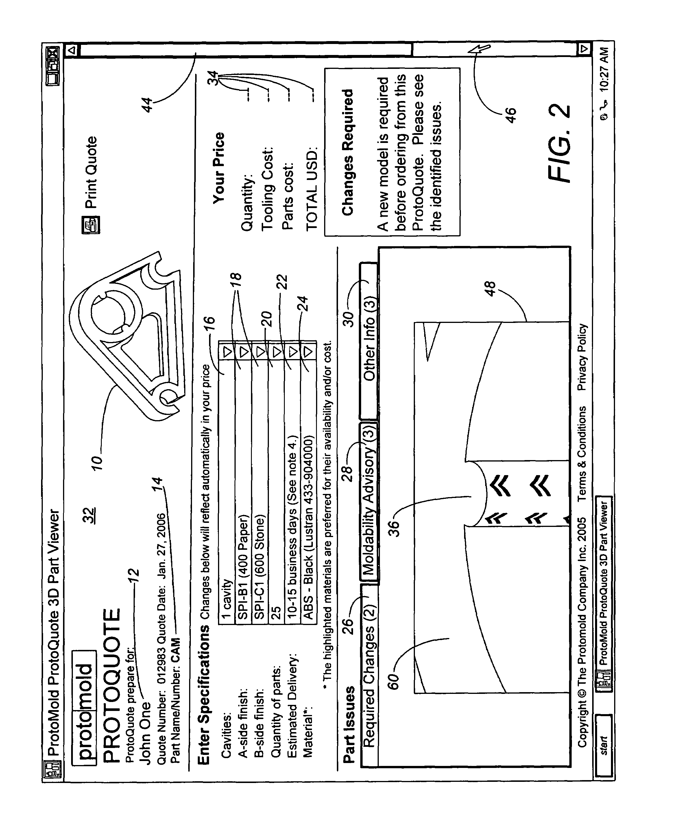
[0013]The quoting of the mold and / or manufacture for the part 10 may generally proceed with automated systems and methods such as described in U.S. patent application Ser. No. 11 / 338,052, 11 / 114,893, 11 / 074,388, 11 / 035,648, 10 / 970,130, 10 / 325,286 (now issued as U....


PUM


Abstract

Any issues associated with manufacture of a part are identified and highlighted on a part model. A software method and system then uses motion of the part model for communicating the manufacturability issues to the customer. The motion can include a repositioning of a part rendering to a preferred orientation position, a fly-around so the customer can appreciate the next zoom location, and then a zooming in on the issue desired to be shown. Alternatively or in conjunction with the zooming and fly-around motion, the orientation of the part rendering showing the manufacturability issues can be three-dimensionally manipulated such as with a click-drag-drop command of the customer's computer mouse. By adding a moveable aspect to the communication, customers can much better understand which changes are recommended or required of the part.

Description

CROSS-REFERENCE TO RELATED APPLICATION(S)[0001]None.BACKGROUND OF THE INVENTION[0002]The present invention relates to software supported methods, systems and tools used in the design and fabrication of molds for custom plastic parts, and in presenting information to customers for the customer to make selections to help minimize the cost of the mold and running the customer's part.[0003]Injection molding, among other types of molding techniques, is commonly utilized to produce plastic parts from molds. Companies and individuals engaged in fabricating molds are commonly referred to as “moldmakers.” The moldmaking art has a long history of fairly gradual innovation and advancement. Molds are designed pursuant to a specification of the part geometry provided by a customer; in many cases, functional aspects of the plastic part also need to be taken into account. Historically, moldmaking involves at least one face-to-face meeting between the moldmaker and the customer, with complex commun...

Claims


Application Information

Patent Timeline
Patent Type & Authority Patents(United States)
IPC IPC(8): G06F19/00
CPCG06F17/50H04N5/2627G06F2217/41G06F2217/04G06F30/00G06F2111/02G06F2113/22
Inventor LUKIS, LAWRENCE J.HARTLOFF, MATTHEW
Owner PROTOLABS INC
Why Eureka
Try Eureka