Quick change module with adjustable former attachments

a technology of former attachments and quick change modules, which is applied in the direction of packaging machines, transportation and packaging, and packaging, etc., can solve the problems of significantly more expensive than conventional packaging, expensive and relatively slow 3-piece construction, and not particularly stable prior art packages when standing on one end

Inactive Publication Date: 2007-11-27
FRITO LAY NORTH AMERICA INC
View PDF61 Cites 68 Cited by
  • Summary
  • Abstract
  • Description
  • Claims
  • Application Information

AI Technical Summary

Benefits of technology

[0017]The proposed invention involves producing a vertical stand-up pouch or gusseted flat bottom bag constructed of a single sheet of material using a slightly modified vertical form, fill, and seal machine comprising a quick change module which includes at least one pair of adjustable forming plates located below the forming tube. A gusseting mechanism mounted to the frame of the machine can be positioned between each pair of forming plates to impart a vertical crease or tuck along the length of the bag while it is being formed and advanced down the forming tube of the machine. The quick change module may further comprise a tension bar on an opposing side from the adjustable forming plates for making vertical stand-up pouches. The module easily attaches to the bottom of the forming tube, thereby making conversion back to a standard pillow bag manufacture simple and quick.
[0018]Each pair of forming plates is attached to the module by means of a corresponding pair of slotted brackets, which are connected to the module. Each pair of slotted brackets are oriented at converging angles to one another so that the lateral distance between the forming plates can be adjusted by positioning each forming plate at selected points along its respective slotted bracket. By adjusting the lateral distance between the forming plates, the size and depth of the crease or fold imparted in conjunction with the gusseting mechanism can be increased or decreased. In a preferred embodiment, each of the brackets are attached to a separate horizontal hinge, allowing the attached forming plates to fold inward when a traverse seal in formed, thereby preventing the packaging film from being ripped by the free ends of the forming plates.
[0020]In accordance with another aspect of the method of the present invention, the size of a resulting package can be increased by extending the advance of the tube of packaging film between forming the transverse seals. In general, the bases of larger sized bags require deeper gussets to enhance the stability characteristics of the bags. By adjusting the lateral separation of the forming plates, the size of the gusseted base can be increased or decreased in proportion to the size of the resulting package, thereby enhancing the overall stability of the package when placed on display.
[0021]A zipper seal or reclose seal can be easily added to the construction of such a vertical stand-up bag since the zipper seal can accompany the single sheet of film in a continuous strip along one edge of the film.
[0022]The methods disclosed and the pouches and bags formed as a consequence are a substantial improvement over prior art horizontal stand-up pouches and flat bottom bags. The quick change module featuring adjustable forming plates enables a single vertical form, fill and seal machine to produce a wide assortment of differently sized bags having gussets of variable depth. The methods works on existing vertical form, fill, and seal machines requiring very little modification. There are minimal moving parts and no jaw carriage modifications involved. The vertical form, fill, and seal machine can be easily converted back to a conventional pillow pouch configuration by simply disconnecting the quick change module from the bottom of the forming tube. The same metalized or clear laminations used as materials in pillow pouches can also be used with the invention therefore saving in per bag cost. The invention allows for the formation of differently sized bags that emulate a horizontal stand-up pouch using a completely different method that takes advantage of the economics of vertical form, fill, and seal machine technology.

Problems solved by technology

Because of the narrow, single edge base on the package shown in FIG. 3a formed by the bottom transverse seal 33, such prior art packages are not particularly stable when standing on one end.
Manufacture of such horizontal stand-up pouches, however, does not involve the use of standard vertical form, fill, and seal machines but, rather, involves an expensive and relatively slow 3-piece construction using a pouch form, fill, and seal machine.
The requirement that such horizontal stand-up pouch be constructed of three pieces results in a package that is significantly more expensive to construct than a standard form, fill, and seal vertical flex bag.
Further disadvantages of using horizontal stand-up pouches include the initial capital expense of the horizontal stand-up pouch machines, the additional gas flush volume required during packaging as compared to a vertical flex bag, increased down time to change the bag size, slower bag forming speed, and a decreased bag size range.
However, the prior art method of making a flat bottom bag has a number of significant drawbacks.
For example, the capital expense for modifying the vertical form, fill, and seal machine to include the moving triangular-shaped devices is approximately $30,000.00 per machine.
The addition of all of the moving parts required for the triangular-shaped device to move in and out of position during each package formation cycle also adds complexity to the vertical form, fill, and seal machine, inevitably resulting in maintenance issues.

Method used


Image

  • Quick change module with adjustable former attachments
  • Quick change module with adjustable former attachments
  • Quick change module with adjustable former attachments

Examples


Embodiment Construction

A. Vertical Stand-Up Pouch

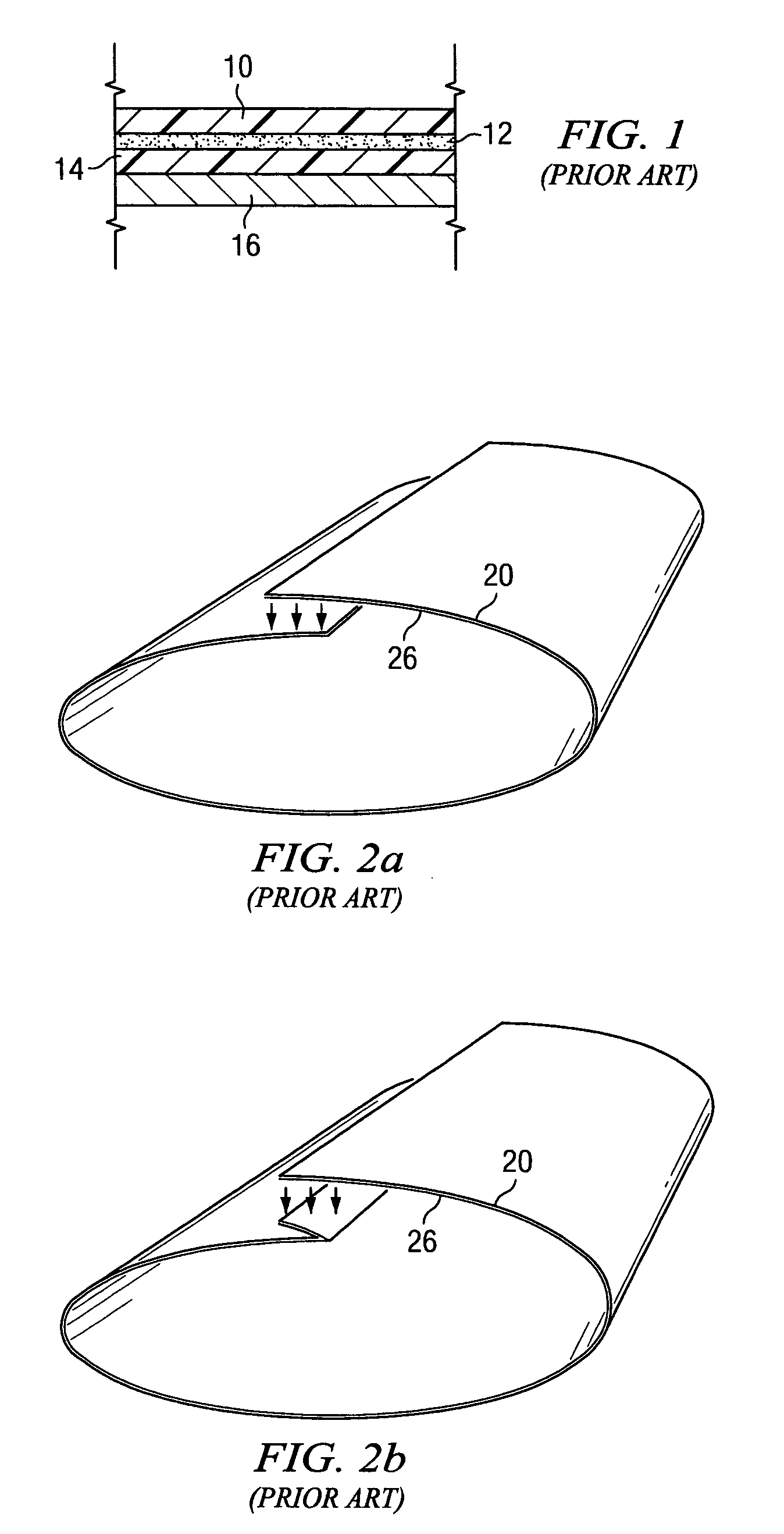
[0055]FIGS. 5a, 6a and 6b illustrate two embodiments of the basic components used with the method of the proposed invention as it relates to the manufacture of a vertical stand-up pouch. The same reference numbers are used to identify the same corresponding elements throughout all drawings unless otherwise noted. FIG. 5a is a schematic cross-section of a tube of packaging material (film) formed by the present invention method. The tube of packaging film shown in FIG. 5a is illustrated as a cross-sectional area immediately below the forming tube 101 of FIGS. 6a and 6b (shown in phantom in FIG. 5a). The tube of packaging film comprises an outer layer 116 and an inner layer 110, and can comprise material typically used in the field of art for making a standard vertical flex bag, such as discussed in relation to FIG. 1. The tube in FIG. 5a has been formed by sealing one sheet of film with a vertical back seal, as previously described with regard to discussions ...


PUM

PropertyMeasurementUnit
converging angleaaaaaaaaaa
distanceaaaaaaaaaa
converging angleaaaaaaaaaa

Abstract

A quick change module operable for being removably attached to and extending below a forming tube of a conventional vertical form, fill, and seal machine to produce a wide assortment of differently sized vertical stand-up pouches or gusseted flat bottom bags. The quick change module comprises at least one pair of adjustable forming plates located below the forming tube. The lateral distance between each pair of forming plates can be adjusted by shifting the position of each forming plate along a corresponding slotted bracket. A gusseting mechanism mounted to the frame of the machine can be positioned between each pair of forming plates imparting a vertical crease along the length of the bag while it is being formed and advanced down the forming tube of the machine. By adjusting the lateral separation of the forming plates, the size of the vertical crease can be adjusted such that the resulting gusseted base is increased or decreased in proportion to size of the resulting package, thereby enhancing the overall stability of the package when placed on display.

Description

CROSS-REFERENCE TO RELATED APPLICATIONS[0001]This application is a continuation-in-part of U.S. patent application Ser. No. 10 / 778,839, filed on Feb. 13, 2004, which, in turn, is a divisional application of U.S. patent application Ser. No. 10 / 100,370, filed on Mar. 18, 2002 (now U.S. Pat. No. 6,722,106).BACKGROUND OF THE INVENTION[0002]1. Technical Field[0003]The present invention relates to a modified vertical form, fill, and seal packaging machine and method for using the same to construct a vertical stand-up pouch and a gusseted flat bottom bag , that provides for a single piece construction of a vertical stand-up bag suitable for retail snack food distribution. The invention allows for use of existing film converter and packaging technology to produce a stand-up package with minimal increased costs and minimal modifications.[0004]2. Description of the Related Art[0005]Vertical form, fill, and seal packaging machines are commonly used in the snack food industry for forming, filli...

Claims


Application Information

Patent Timeline
Patent Type & Authority Patents(United States)
IPC IPC(8): B65B9/20B65B9/22
CPCB65B9/20B65B9/2042B65B9/213B65D75/008B65B59/04B65B65/06B65B9/22
Inventor KOHL, GARRETT WILLIAMREAVES, JERRY MIKETUCKER, STEVEN KENNETHWHITE, JERYL EDWIN
Owner FRITO LAY NORTH AMERICA INC
Why Eureka
Try Eureka