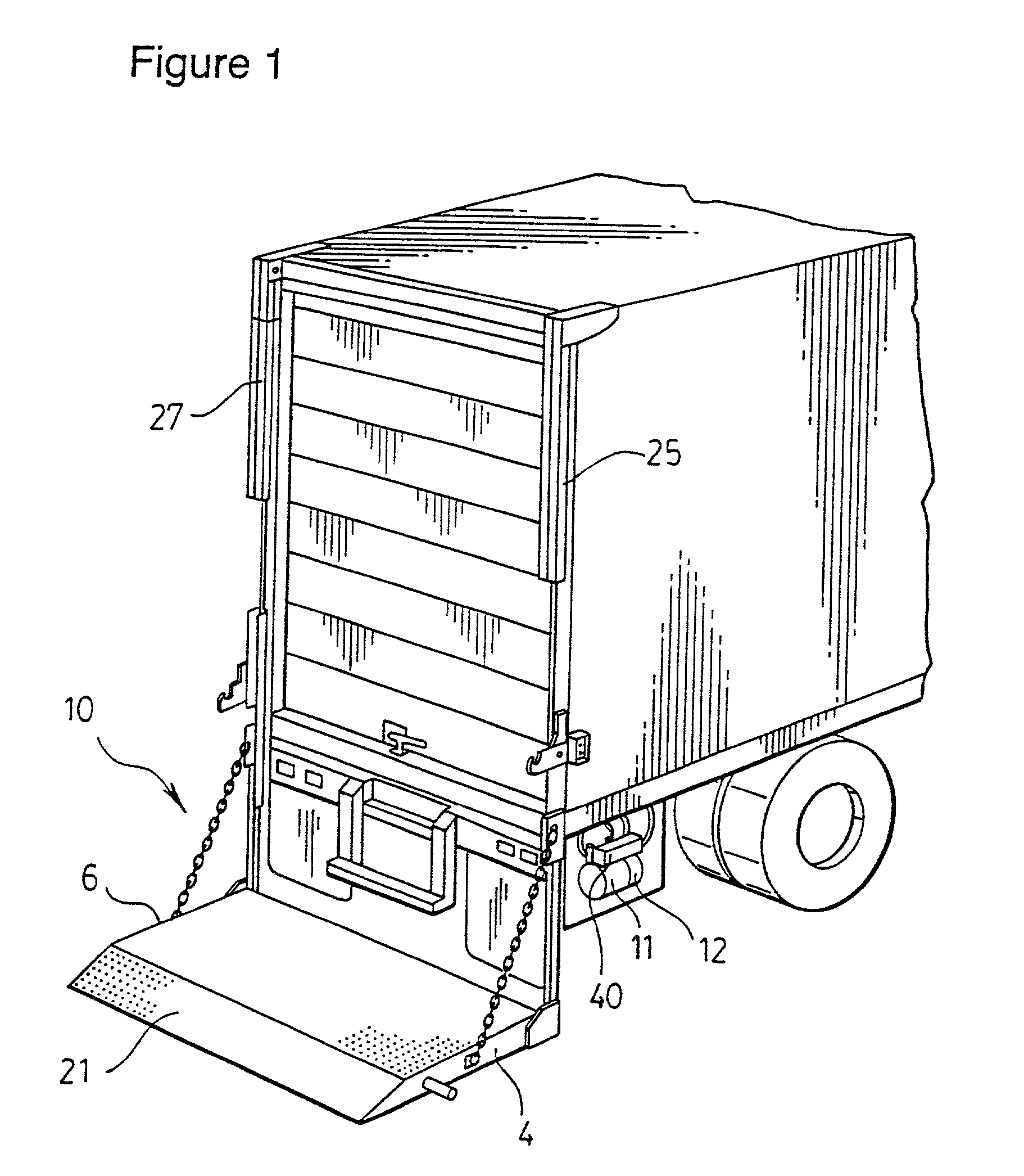
[0005]In one of its broad embodiments the present invention comprises a hydraulic platform lift for a
truck or
truck trailer for raising and lowering a platform, having a pair of hydraulic cylinders and a positive displacement valve means coupled to each of the hydraulic cylinders in a particular manner which serves to assist in equal synchronized movement of piston members within the hydraulic cylinders regardless of the difference in forces which may be applied to the individual cylinders due to uneven distribution of load on a platform.
[0012]Advantageously, the hydraulic platform lift of the present invention having a
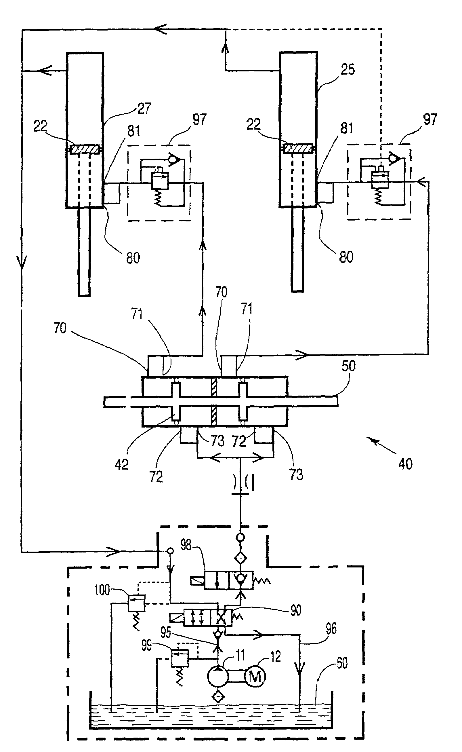
hydraulic circuit incorporating a positive displacement means as described above, is able to accomplish the synchronized movement of the piston members as was accomplished by each of the two prior art configurations described above, but in a completely different manner. The
hydraulic circuit of the present invention provides an
advantage over the circuit shown in FIG. 3 (“Prior Art”) in that it requires only one pump, not two as required in the circuit disclosed in FIG. 3 (“Prior Art”), thereby resulting in an immediate
cost savings of the hydraulic circuit of the present invention over the configuration shown in FIG. 3 (“Prior Art”). Moreover, due to inherent tolerances in the manufacture of pumps, pumps are never completely identical, and even though two pumps may be fixedly coupled together so as to run at the same speed, particularly at low speeds and
low volume flows, pump output may vary somewhat from one pump to another, thereby causing non-synchronized movement of piston members within the respective cylinders. The hydraulic circuit for the platform lift of the present invention utilizes only one pump and accordingly is thereby able to completely eliminate this problem of uneven output from individual pumps.
[0013]The hydraulic lift of the present invention, as will be more fully described below, is particularly adapted for providing both “power up” and “power down”capability. In particular, in a further embodiment, the aperture for each cylinder member of the positive displacement valve (which permits the ingress of
hydraulic fluid from the pump means for raising of the platform) permits egress of fluid from the cylinder member when said platform is desired to be lowered.
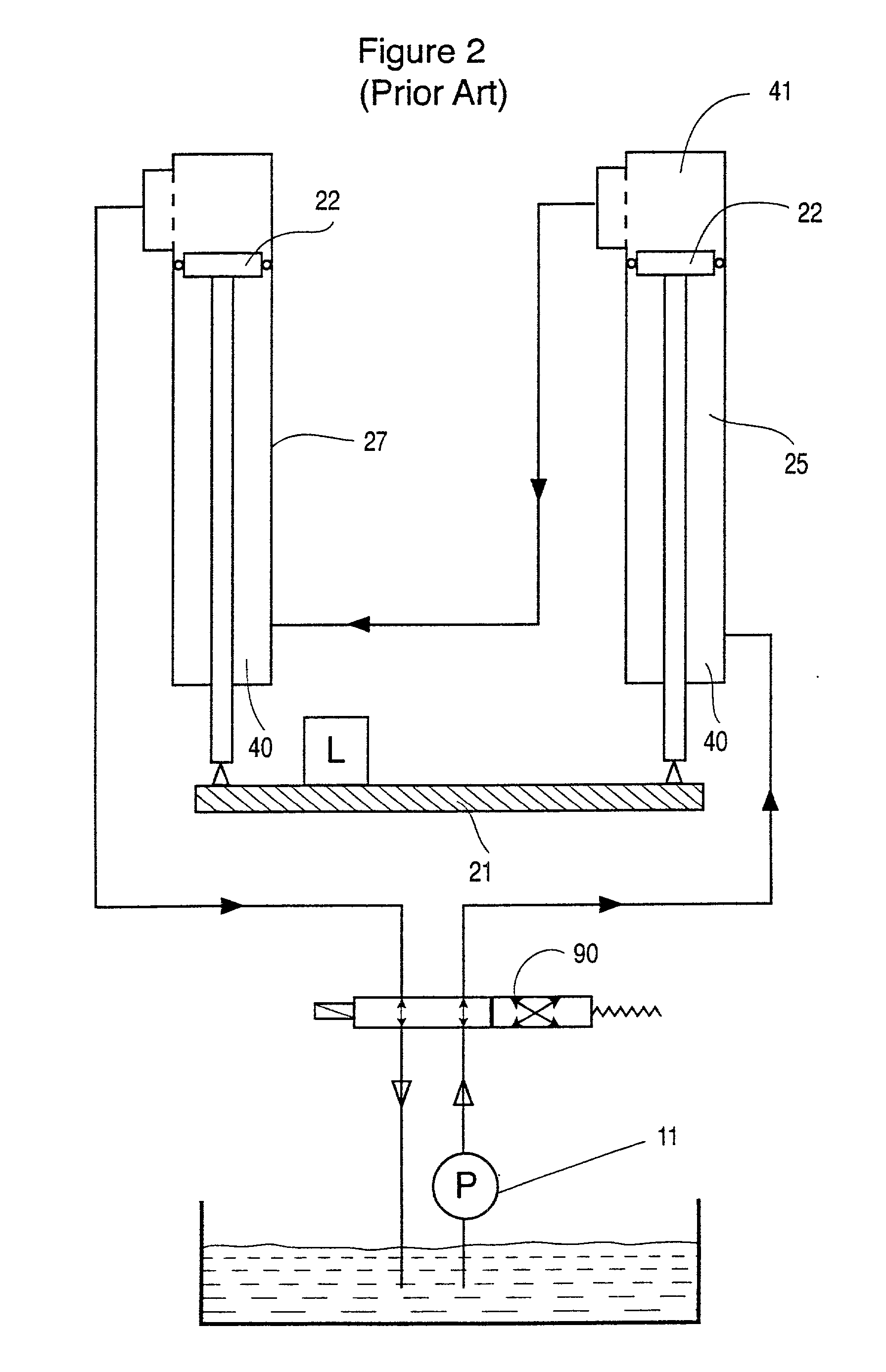
[0016]Π(4)2Π(4)2-Π(2)2(ie.aratioof1.33:1)or stated otherwise, a
resultant 33% increase in the force applied by the positive displacement valve is theoretically obtainable on the hydraulic fluid contained therein (a 16.5% increase in the force to each of two cylinders) than would otherwise be the case if the fluid was simply supplied by the pump means directly to the hydraulic cylinders, or if the shaft extended from both sides of the piston. Accordingly, for the same amount of necessary pressure, a lower pressure pump can be used resulting in a definite
cost savings over what would otherwise be a higher pressure pump that would be required to produce a pressure necessary to lift a given load. Thus by being able to size a smaller pump for a hydraulic cylinders of given lifting capability, the hydraulic circuit of the present invention possesses a definite
advantage over prior art hydraulic lifts having the hydraulic circuit shown in FIG. 2 (“Prior Art”).
[0018]As a means of being able to re-align or “re-synchronize” the piston members within the hydraulic cylinders, the present invention provides, in a preferred embodiment, that the cylinder members of the positive displacement means each possess piston phasing means
proximate at least one end thereof to permit resynchronization (ie. realigned positioning) of the piston members within the first and second hydraulic cylinders relative to each other, in order to overcome the problem of the piston members becoming out of alignment due to differences in operation between the two hydraulic cylinders. More particularly in a preferred embodiment, the piston phasing means in each cylinder member comprises a pair of apertures
proximate one end of each cylinder member, spaced apart from each other along a longitudinal axis of the cylinder member. Although both apertures are situate close to one end of a corresponding cylinder member, the aperture most
proximate the end of the cylinder member is preferably larger in area and permits more flow of hydraulic fluid there through than the other aperture. The longitudinal spacing of the apertures is such that the piston when it moves to the end of the corresponding cylinder member will move to a position intermediate the longitudinal spacing of the two apertures, thereby allowing hydraulic fluid to escape from both apertures when the piston is at its extremity of travel at one end of the cylinder member. Accordingly, in operation, the piston phasing means of each cylinder member, when the pistons of each cylinder member move to a respective end (ie maximum extremity) of the corresponding cylinder member, permits hydraulic fluid to continue to be supplied to the hydraulic cylinders. In the event that one of the
hydraulic cylinder members has reached the end of its travel (ie when one side of the platform has thereby been moved to the maximum raised or lowered position), with such piston phasing means pressurized hydraulic fluid will continue to flow to such
hydraulic cylinder, to permit it to “catch up” and permit it too to reach the maximum extent of its travel, thereby “resynchronizing” the piston members in such hydraulic cylinders and thereby re-leveling the attached platform.
[0021]In yet another embodiment of the invention, the hydraulic cylinders themselves may possess piston member phasing means (which in the preferred embodiment are a pair of apertures longitudinally spaced apart along the longitudinal axis of the hydraulic cylinder) at only one end of both hydraulic cylinders or at both ends of each hydraulic cylinder. This feature may be used with or without piston phasing means being incorporated on the positive displacement valve. In particular, piston member phasing in the hydraulic cylinders, when used with piston phasing on the positive displacement valve, is advantageous in situations where one of the piston members contained in the hydraulic cylinders reaches the top (or bottom) of its
stroke prior to the other piston member, and prior to either piston in the positive displacement valve reaching the extremity of travel. In such condition, by having piston phasing of the piston members in the hydraulic cylinders, hydraulic fluid can continue to be supplied to both hydraulic cylinders, with hydraulic fluid being permitted to escape from one of the apertures of the hydraulic cylinder which has already reached the extremity of travel, thereby permitting both pistons within the respective cylinder members to continue movement.

