
Quadrilateral symmetrical light source

Inactive Publication Date: 2007-11-27
EXCELITAS TECH
View PDF21 Cites 50 Cited by
  • Summary
  • Abstract
  • Description
  • Claims
  • Application Information

AI Technical Summary

Benefits of technology

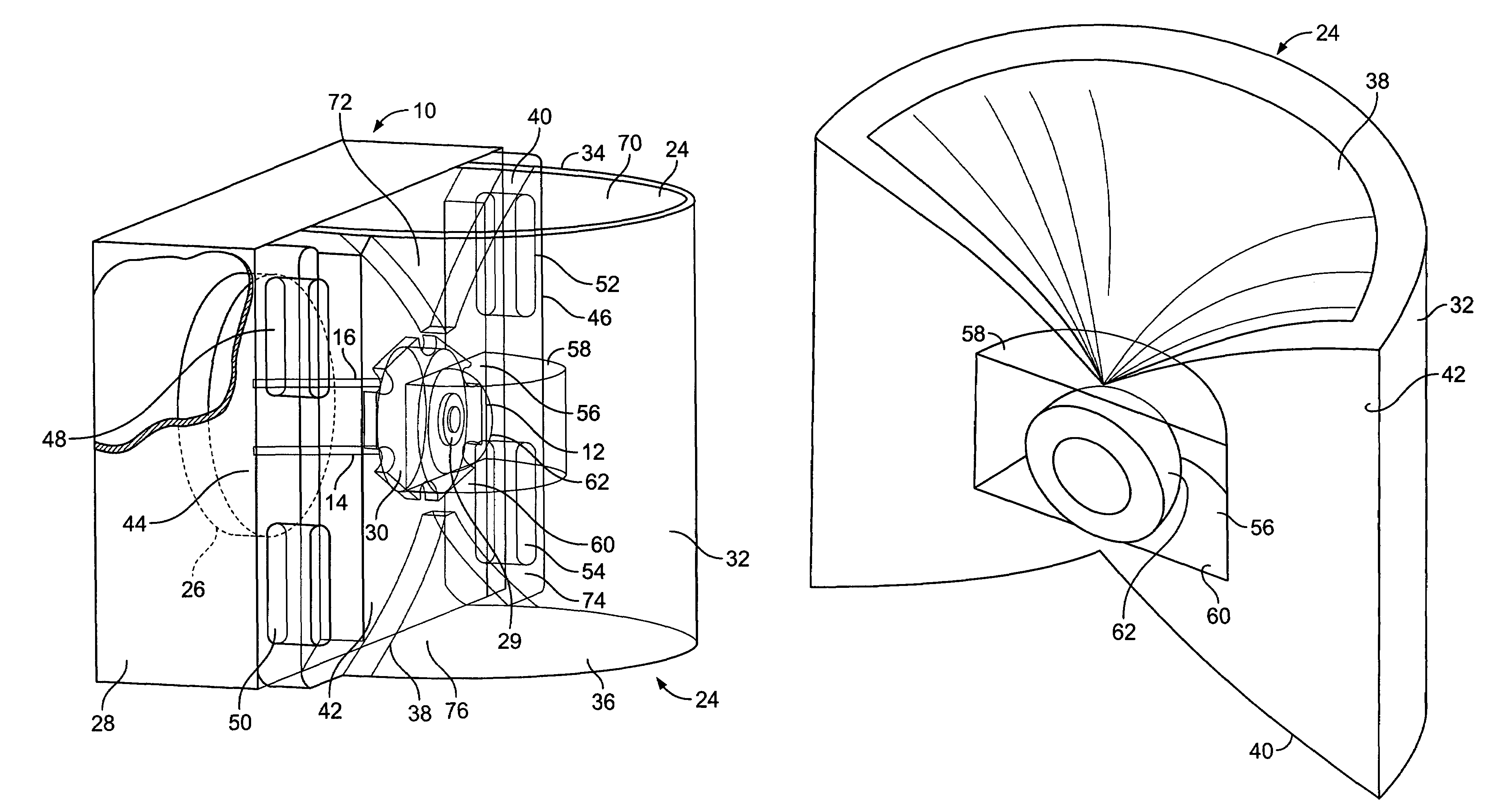
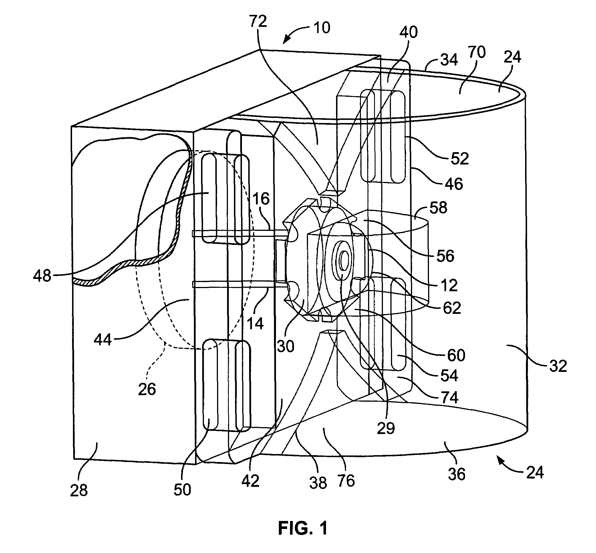
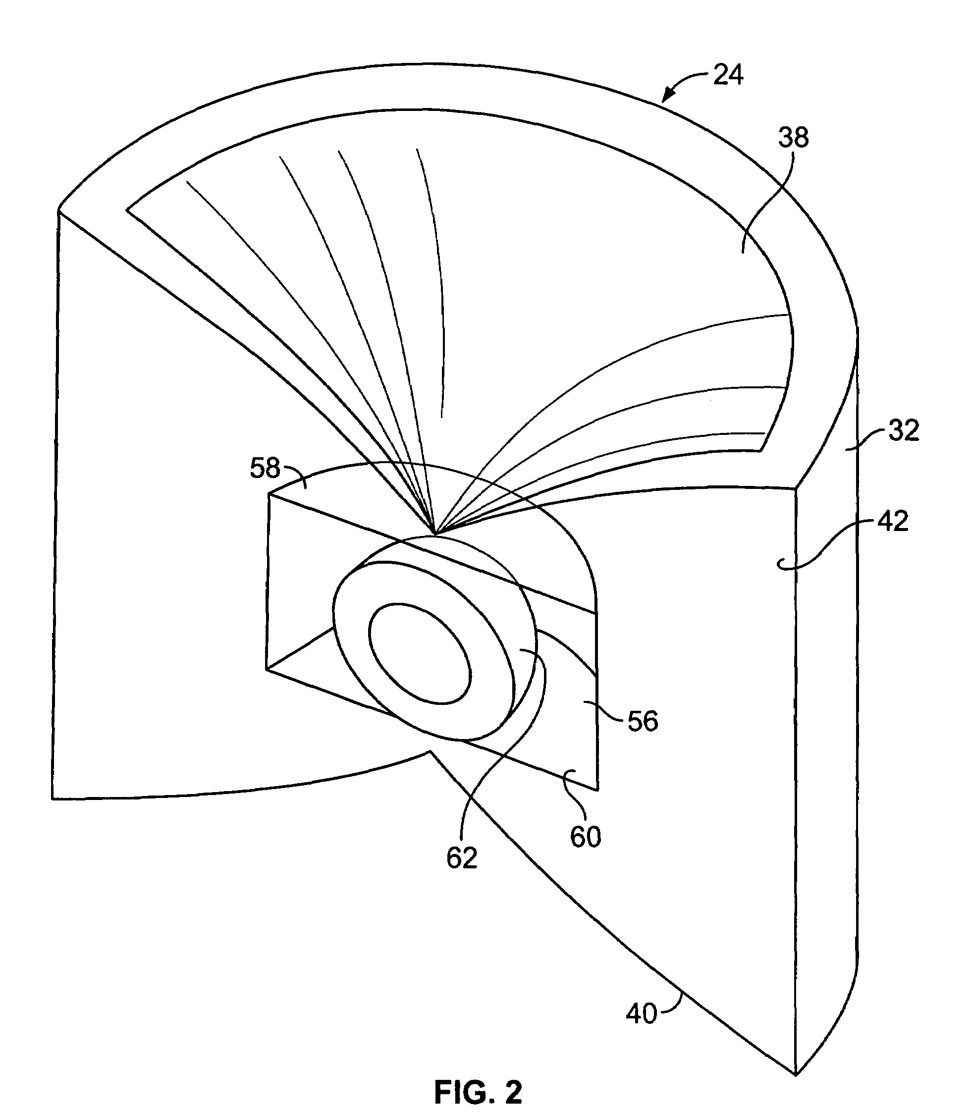
[0007]These needs and others may be met by the present invention, an example of which is a directed light source for efficient light emission. The light source has a planar substrate having a front surface and an opposite back surface. A light emitting device is located on the front surface of the planar substrate. A clear reflector has a back surface facing the front surface of the planar substrate and a semi-cylindrical front surface. The reflector includes a reflecting top surface and an opposite and quadrilaterally symmetrical reflecting bottom surface. The reflector causes light from the light emitting device to be directed out from the cylindrical front surface at a predefined angle.

Problems solved by technology

Other current alternative light sources include xenon lamps which increase light output but require a high operating voltage and has a limited life span.
However, traditional light sources are used for numerous applications which take advantage of some of the characteristics of the light source but are often limited by other characteristics as well.
Traditional light sources have different thermal, optical and geometric limitations that differ greatly from light emitting diodes (LED).
These differences have limited the use of LEDs in traditional lighting applications.
The use of LEDs to replace tradition light applications has been desired, but adaptation of the LEDs to a traditional lighting mounting arrangements has been difficult.

Method used


Image

  • Quadrilateral symmetrical light source
  • Quadrilateral symmetrical light source
  • Quadrilateral symmetrical light source

Examples


Embodiment Construction

[0023]While the present invention is capable of embodiment in various forms, there is shown in the drawings and will hereinafter be described a presently preferred embodiment with the understanding that the present disclosure is to be considered as an exemplification of the invention, and is not intended to limit the invention to the specific embodiment illustrated.

[0024]FIG. 1 shows a lighting device 10 which is one example of the present invention. The lighting device 10 is centered around an LED 12 which is any semi-conductor, solid state light source such as a flat LED. The LED 12 will preferably have a lambertian distribution for the widest angle distribution of light. The LED 12 is coupled to a power source via two electrical leads 14 and 16. The LED 12 is affixed to a planar substrate 18. The planar substrate 18 is typically made from a highly thermally conductive material such as aluminum. The planar substrate 18 has a back surface with an opposite planar front surface. Of c...


PUM


Abstract

A reflector for focusing light emitted from a light source in a generally planar direction is disclosed. The reflector is matched with the light source that is preferably a light emitting diode (LED) mounted on a substrate. The reflector is mounted over the LED on the substrate. The reflector is made of a clear material. The reflector has a semi-cylindrical front surface and a back surface with an indentation that is compatible with the light source. The reflector has a top reflecting surface divided into two quadrants and a bottom reflecting surface divided into two quadrants. The top quadrants and bottom quadrants are symmetrical in shape and reflect light emitted from the light source in a substantially horizontal plane. The reflecting surfaces may be TIR based or they may be coated with a reflective material in order to focus light from the LED.

Description

RELATED APPLICATION[0001]This application claims priority from Provisional Application No. 60 / 448,090 filed on Feb. 19, 2003 which is incorporated by reference.FIELD OF INVENTION[0002]The present invention relates generally to the field of light sources. More specifically, the present invention is directed to a light source having a quadrilateral symmetrical reflector to allow focused light output.BACKGROUND OF INVENTION[0003]Light emitting diodes (LEDs) are well known solid state light sources. LEDs have many advantages over traditional sources such as incandescent bulbs as they are cheaper to produce, are more robust, and require less power. Other current alternative light sources include xenon lamps which increase light output but require a high operating voltage and has a limited life span. However, traditional light sources are used for numerous applications which take advantage of some of the characteristics of the light source but are often limited by other characteristics as...

Claims


Application Information

Patent Timeline
IPC IPC(8): F21V7/04
CPCF21K9/00F21V5/04F21V5/046G02B19/0061G02B19/0028F21V7/0091F21S48/215F21S48/328F21V29/004F21W2111/00F21Y2101/02F21K9/68F21S43/14F21V29/70F21Y2115/10
Inventor RUFFIN, MARVINFIELDS, CRAIG
Owner EXCELITAS TECH
Learn More