Golf club

a golf club and golf technology, applied in golf clubs, golf, sport apparatus, etc., can solve the problems of reducing the travel distance and deteriorating directional stability, and achieve the effect of increasing the effective loft angle of the head, great launch angle, and low back spin ra

Active Publication Date: 2007-11-27
SUMITOMO RUBBER IND LTD
View PDF7 Cites 21 Cited by
  • Summary
  • Abstract
  • Description
  • Claims
  • Application Information

AI Technical Summary

Benefits of technology

[0034]As shown in FIG. 6A and FIG. 6B, due to the centrifugal force during the swing, the center of gravity of the head G is apt to be positioned on an extended shaft line z1 that is an extended line of a shaft axis line z in the vicinity of the grip 4. The aptness of the center of gravity of the head G to be positioned on the extended shaft line z1 results in bending of the shaft 3 in a direction of the swing (ahead in a direction of the down swing). In other words, the aptness of the center of gravity of the head G to be positioned on the extended shaft line z1 results in bending of the shaft 3 such that the effective loft angle of the head is increased. As is seen from the comparison of FIG. 6A with FIG. 6B, greater depth of the center of gravity D exerts a greater effect to apt to result in the head trajectory hk of an upper blow in the vicinity of the impact position (hereinafter, also referred to as upper blow effect). The depth of the center of gravity D2 of the golf club 13 shown in FIG. 6B is greater than the depth of the center of gravity D1 of a golf club 12 shown in FIG. 6A. When the angle formed by the intersection of the head trajectory hk of the golf club 13 with the horizontal line s is designated as θ2, and the angle formed by the intersection of the head trajectory hk of the golf club 12 with the horizontal line s is designated as θ1, a relationship of θ2>θ1 tends to be found.
[0035]For reference, in the golf club 1 in a static state, the shaft axis line z and the extended shaft line z1 are identical because the shaft 3 is not bent.
[0036]By specifying the flexural rigidity value EIt to be equal to or less than 1.75×10⁶ (kgf·mm2), the tip part of the shaft 3 becomes flexible, thereby achieving the aforementioned upper blow effect sufficiently. When the head trajectory of an upper blow is attained, initial conditions with a great launch angle and a low back spin rate can be readily achieved. Also, when the flexural rigidity value EIt is specified to be equal to or less than 1.75×10⁶ (kgf·mm2), run of the head 2 is facilitated, and thus, the golf club 1 can be readily handled by many golf players including average handicappers.
[0037]When the flexural rigidity of the tip part of the shaft is excessively low, state of deformation of the shaft becomes hardly unstable due to variation of the swing and the like. Accordingly, directional stability and control performances are deteriorated. By specifying the flexural rigidity value EIt to be equal to or greater than 0.5×10⁶ (kgf·mm2), the flexural rigidity of the tip part of the shaft 3 is secured to be not lower than a given level. Consequently, directional stability and control performances upon hitting may be achieved.
[0038]When the flexural rigidity of the tip part of the shaft becomes excessively great, too low deflection of the shaft may be provided. Accordingly, effect of increasing the head speed by way of restoration of the deflection is hardly achieved. Also, when the deflection of the shaft is excessively low, it becomes hard for the golf players to feel the head weight, and thus, decision on the timing of the swing may be difficult. By specifying the flexural rigidity value EIt to be equal to or less than 1.75×10⁶ (kgf·mm2), the effect of increasing the head speed is readily achieved, and thus, the timing of the swing may be readily decided.
[0039]FIG. 7 perspectively shows the center of gravity of the head G located inside of the head 2. The center of gravity of the head G is located on the back side of the head from the reference plane K, and is located on the toe side from an axis line z2 of the shaft hole 11. As described above, due to centrifugal force during the swing, the center of gravity of the head G is apt to be positioned on the extended shaft line z1. The centrifugal force during the swing causes the following (1) to (3) events.

Problems solved by technology

When a club with inappropriate shaft flex is used, the travel distance may be reduced, or the directional stability may be deteriorated.

Method used


Image

  • Golf club
  • Golf club
  • Golf club

Examples


example 1

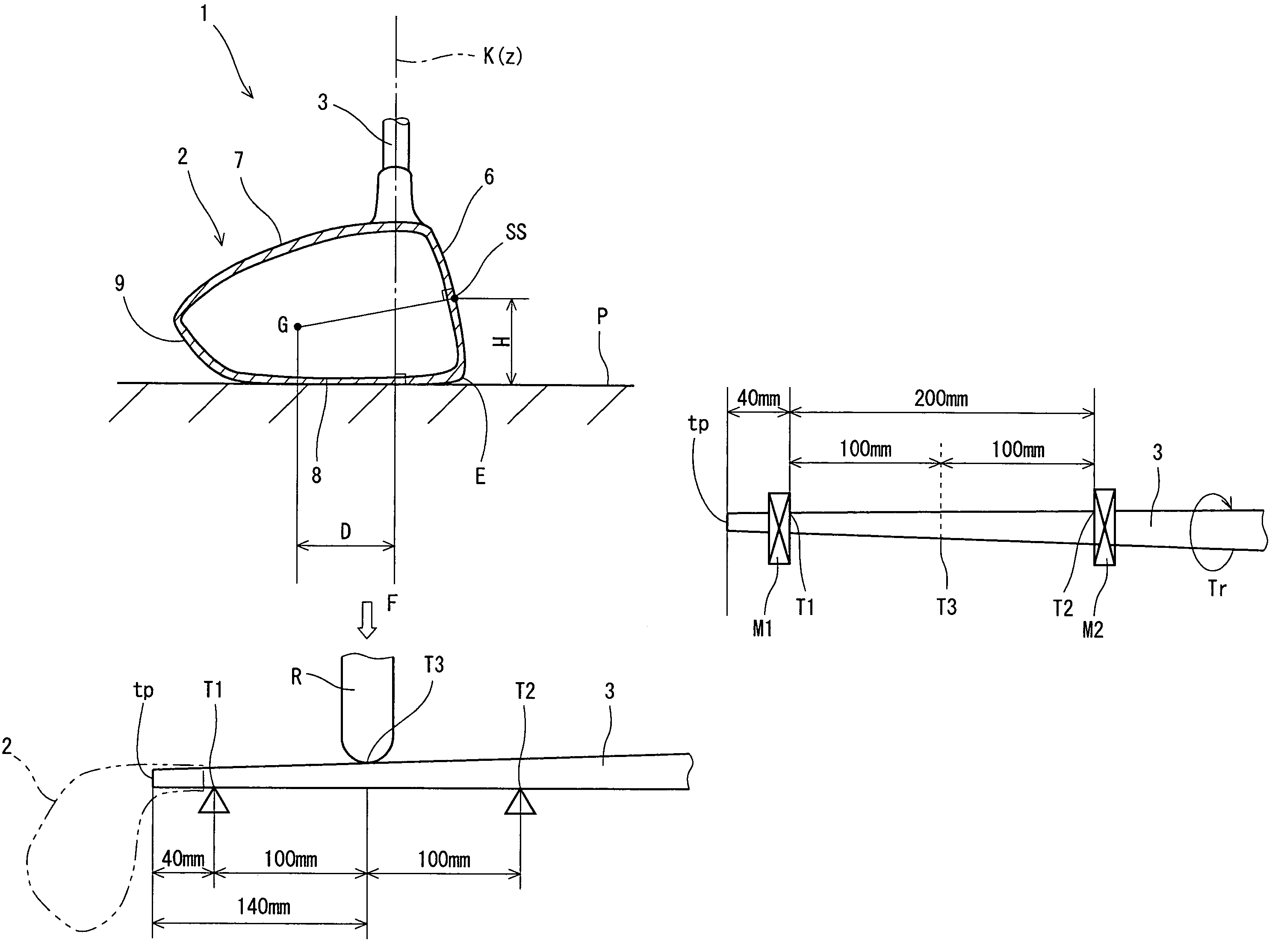
[0096]A head had a three-piece structure including a head main body, a face member and a crown member manufactured by casting using 6-4Ti (Ti-6Al-4V). The face member was produced by subjecting a rolled material of 6-4Ti to a milling processing followed by press molding. The face member and the head main body were joined together by plasma welding. The crown member was produced by laminating the pre-preg sheets of CFRP (carbon fiber reinforced plastic) followed by press molding. The head main body was adhered to the crown member using an adhesive. The head had a volume of 420 cc, and a loft angle (real loft angle) of 10°. A recessed part was provided on the backside of the sole, and to this recessed part was injected a heavy load made of a W—Ni alloy. By regulating the weight of the heavy load and the wall thickness of the side portion, the weight at the depth of the center of gravity D was adjusted, and setting of the depth of the center of gravity D as shown in Table 1 below was e...

examples 2 to 5

[0098]Golf clubs were obtained in a similar manner to Example 1 except that the depth of the center of gravity D, the flexural rigidity value EIt and the torsional rigidity value GIt were as shown in Table 1.


PUM


Abstract

A reference state is envisioned in which a golf club is placed on a horizontal plane P with a predetermined lie angle and face angle, and the shaft axis line thereof is disposed within a reference plane that is perpendicular to the horizontal plane P. A center of gravity of the head G is positioned on the back side of the head from the reference plane, and a depth of the center of gravity D that is a distance between the reference plane and the center of gravity of the head G is 20 mm or greater and 30 mm or less. The golf club has a flexural rigidity value EIt (kgf·mm2) of the shaft at a position T3 140 mm away from the tip on the head side being 0.5×10⁶ or greater and 1.75×10⁶ or less. More preferably, a value of a ratio (GIt / EIt) of the flexural rigidity value EIt to a torsional rigidity value GIt of the shaft at a position 140 mm away from the tip on the head side is specified to be 0.8×10⁻² or greater and 1.2×10⁻² or less.

Description

[0001]This application claims priority on Patent Application No. 2005-252006 filed in JAPAN on Aug. 31, 2005, the entire contents of which are hereby incorporated by reference.BACKGROUND OF THE INVENTION[0002]1. Field of the Invention[0003]The present invention relates to a golf club which can result in increase of the travel distance.[0004]2. Description of the Related Art[0005]Travel distance of golf balls attained through hitting with a golf club is principally determined by initial conditions of the ball. The initial conditions of the ball include initial ball speed, launch angle and spin rate upon hitting. Even though the initial ball speed is constant, the travel distance is increased through optimizing the launch angle and spin rate. In general, it has been known that greater launch angle and lower back spin rate can increase the travel distance.[0006]JP-A No. H11-123255 discloses a technique developed in an attempt to achieve a great launch angle and low back spin rate by in...

Claims


Application Information

Patent Timeline
Patent Type & Authority Patents(United States)
IPC IPC(8): A63B53/04A63B53/10A63B102/32
CPCA63B53/00A63B53/10A63B2209/023A63B2059/0081A63B59/0014A63B60/10A63B60/06A63B60/08A63B60/0081A63B60/00
Inventor OYAMA, HITOSHI
Owner SUMITOMO RUBBER IND LTD
Why Eureka
Try Eureka