Method and apparatus for dual polarization imaging

a dual-polarization imaging and imaging method technology, applied in the field of optoelectronic imaging devices, can solve the problems of optical aberration, different magnification, different magnification, alignment and registration of the resulting images using separate detector arrays,

Active Publication Date: 2007-11-27
GENERAL ATOMICS
View PDF6 Cites 19 Cited by
  • Summary
  • Abstract
  • Description
  • Claims
  • Application Information

AI Technical Summary

Benefits of technology

[0012]In a further embodiment, the invention may be characterized as an imaging system including a field stop located at a first image plane adapted to limit a size of an incident light ray bundle passing through an aperture thereof, collimating optics adapted to collimate the incident light ray bundle to the polarization discriminating element, and a birefringent element adapted to angularly refract the incident light ray bundle into a first ray bundle having a first polarization traveling in a first direction and a second ray bundle having a second polarization traveling in a second direction, the first polarization and the second polarization are orthogonal to each other. The system also includes focusing optics adapted to focus the first ray bundle and the second ray bundle to an image detector, the image detector located at a second image plane and adapted to receive the first ray bundle and the second ray bundle such that the first ray bundle forms a first image at a first region of the image detector and the second ray bundle forms a second image at a second region the image detector. The first image and the second image are laterally displaced from each other at the second image plane and do not overlap. The first image is continuous across the first region and the second image is continuous across the second region of the image detector. The field stop limits the incident light ray bundle such that a polarization filter is not required after the birefringent element to prevent crosstalk.

Problems solved by technology

However, such systems suffer from the lack of inherent alignment of the two optical branches when acquiring registered images, i.e., alignment and registration of the resulting images using separate detector arrays are difficult to maintain.
Misalignment of one polarization branch relative to the other can result in different magnifications, orientations, rotations, and optical aberrations from one image to its orthogonal polarization counterpart.
However, in such systems, radiometric performance is limited by the extinction ratio performance of these polarization filters, which is often variable depending on wavelength and angle of incidence.
Thus, any light escaping through the polarization filter which should have been eliminated or filtered becomes a significant source of image noise.

Method used


Image

  • Method and apparatus for dual polarization imaging
  • Method and apparatus for dual polarization imaging
  • Method and apparatus for dual polarization imaging

Examples


Embodiment Construction

[0021]The following description is not to be taken in a limiting sense, but is made merely for the purpose of describing the general principles of the preferred embodiments. The scope of the invention should be determined with reference to the claims.

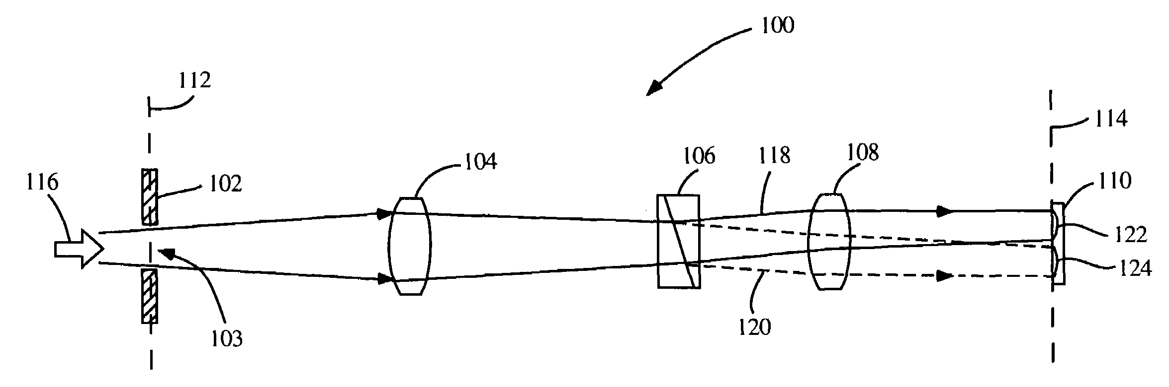
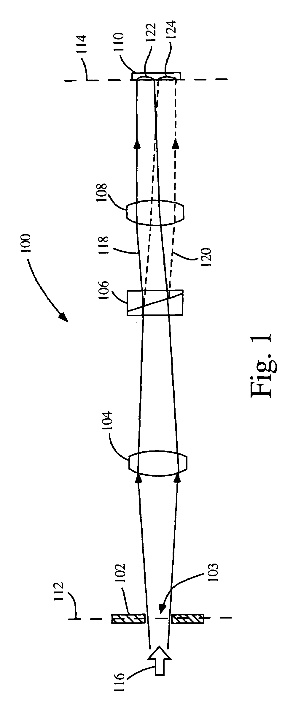
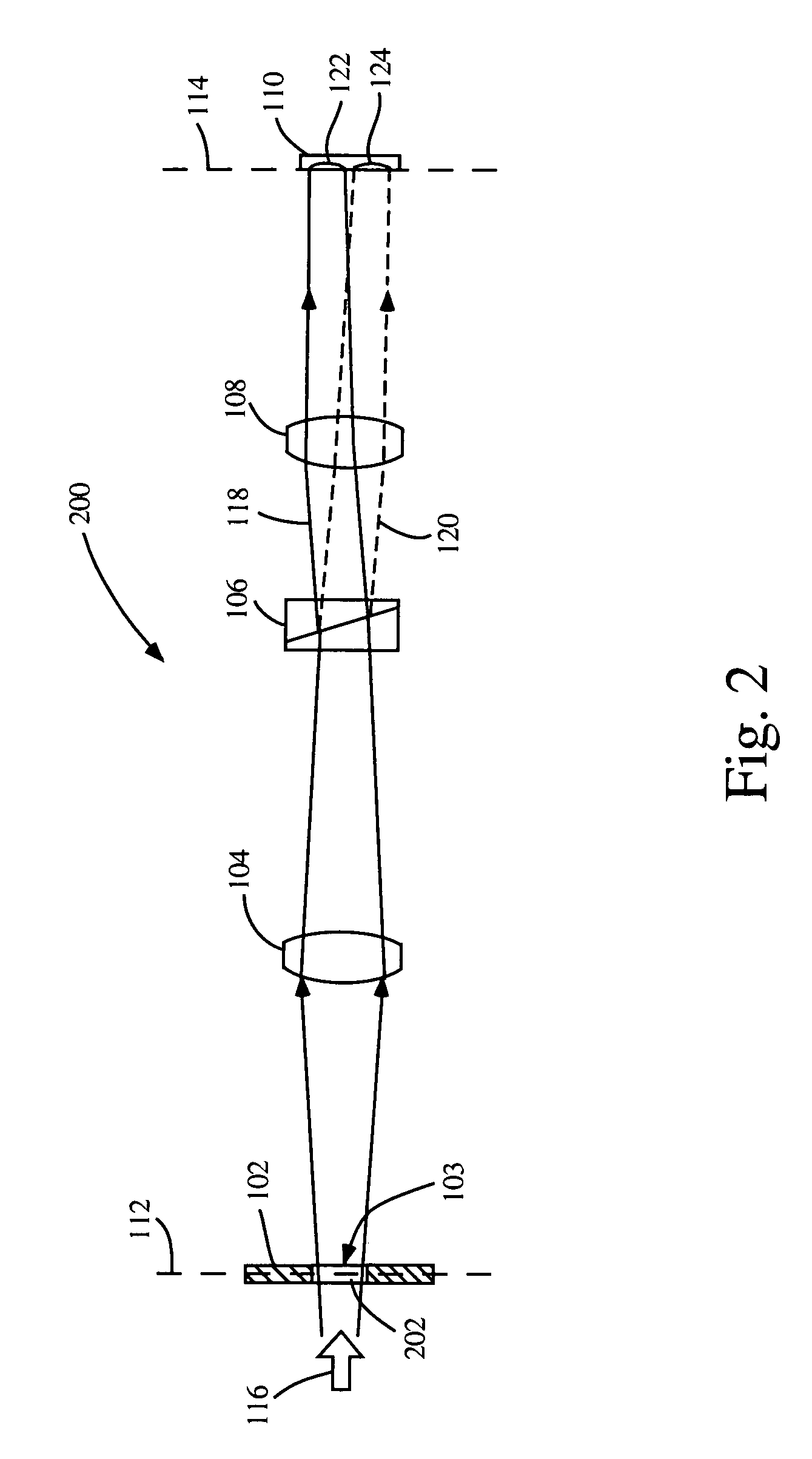
[0022]Referring first to FIG. 1, a diagram is shown of an optical imaging system according to one embodiment of the invention. Illustrated is an imaging system 100 including a field stop 102 having an aperture 103, collimating optics 104, a polarization discriminating element 106, focusing optics 108 and an image detector 110. The field stop 102 is located at a first image plane 112, while the detector surface of the image detector 110 is located at a second image plane 114.

[0023]In accordance with several embodiments of the invention, an imaging system is provided that separates incident light into two polarization states that are simultaneously imaged at separate regions of the single image detector 110 without the need for polarizing...


PUM


Abstract

An imaging system and method for dual polarization imaging is provided. In one implementation, an imaging system includes a field stop located at a first image plane for limiting an incident light ray bundle passing through an aperture thereof and a polarization discriminating element adapted to separate the incident light ray bundle into a first ray bundle having a first polarization traveling in a first direction and a second ray bundle having a second polarization traveling in a second direction. The system also includes an image detector located at a second image plane to receive the first and second ray bundles such that the first ray bundle forms a first image at a first region of the image detector and the second ray bundle forming a second image at a second region the image detector, the first and second images laterally displaced from each other at the second image plane.

Description

[0001]The United States Government may have rights in this invention pursuant to Contract No. MDA972-02-C-0066 between the Defense Advanced Research Projects Agency and General Atomics.BACKGROUND OF THE INVENTION[0002]1. Field of the Invention[0003]The present invention relates generally to optoelectronic imaging devices, and more specifically to optoelectronic imaging devices that provide two optical images having two respective polarizations.[0004]2. Discussion of the Related Art[0005]In certain imaging applications, it is desirable to use dual simultaneous images of light having different orthogonal polarizations of light emanating from a particular scene. One approach splits the optical image received at the imaging system into two optical branches or paths, each branch being a separate image having orthogonal polarizations. These separate images are imaged by separate image acquisition devices, such as charge-coupled device (CCD) imagers or other detector arrays. Common devices...

Claims


Application Information

Patent Timeline
Patent Type & Authority Patents(United States)
IPC IPC(8): H01J40/14G02B27/10G02B27/28H01J3/14G01J4/04
CPCG02B27/283G01J4/04
Inventor YAFUSO, EIJI STEVEN
Owner GENERAL ATOMICS
Why Eureka
Try Eureka