Output current sharing

a technology of output current and power regulator, which is applied in the direction of dc-dc conversion, power conversion systems, instruments, etc., can solve the problems of power loss in each of the resistors, inefficiency of paralleling power converters, and loss of power through oring or summing junction devices

Active Publication Date: 2007-11-27
INTERSIL INC
View PDF8 Cites 23 Cited by
  • Summary
  • Abstract
  • Description
  • Claims
  • Application Information

AI Technical Summary

Problems solved by technology

The techniques for paralleling power converters is often inefficient.
The outputs of multiple converters are often combined at an ORing or summing junction or the like, resulting in a loss of power through the ORing or summing junction devices.
For example, the outputs may be combined using a resistor sharing network, resulting in power loss in each of the resistors.
Alternatively, the outputs are coupled together in an OR configuration using ORing diodes or the like, resulting in power loss in each of the diodes.
Such paralleling techniques do not always provide the desired level of current sharing among the converters, particularly during full-load conditions.
Some converters may dominate or overwhelm other converters during certain load conditions, such as full-load or transient load conditions (sudden change in load, such as sudden load increase or decrease).

Method used


Image

  • Output current sharing
  • Output current sharing
  • Output current sharing

Examples


Embodiment Construction

[0020]The following description is presented to enable one of ordinary skill in the art to make and use the present invention as provided within the context of a particular application and its requirements. Various modifications to the preferred embodiment will, however, be apparent to one skilled in the art, and the general principles defined herein may be applied to other embodiments. Therefore, the present invention is not intended to be limited to the particular embodiments shown and described herein, but is to be accorded the widest scope consistent with the principles and novel features herein disclosed.

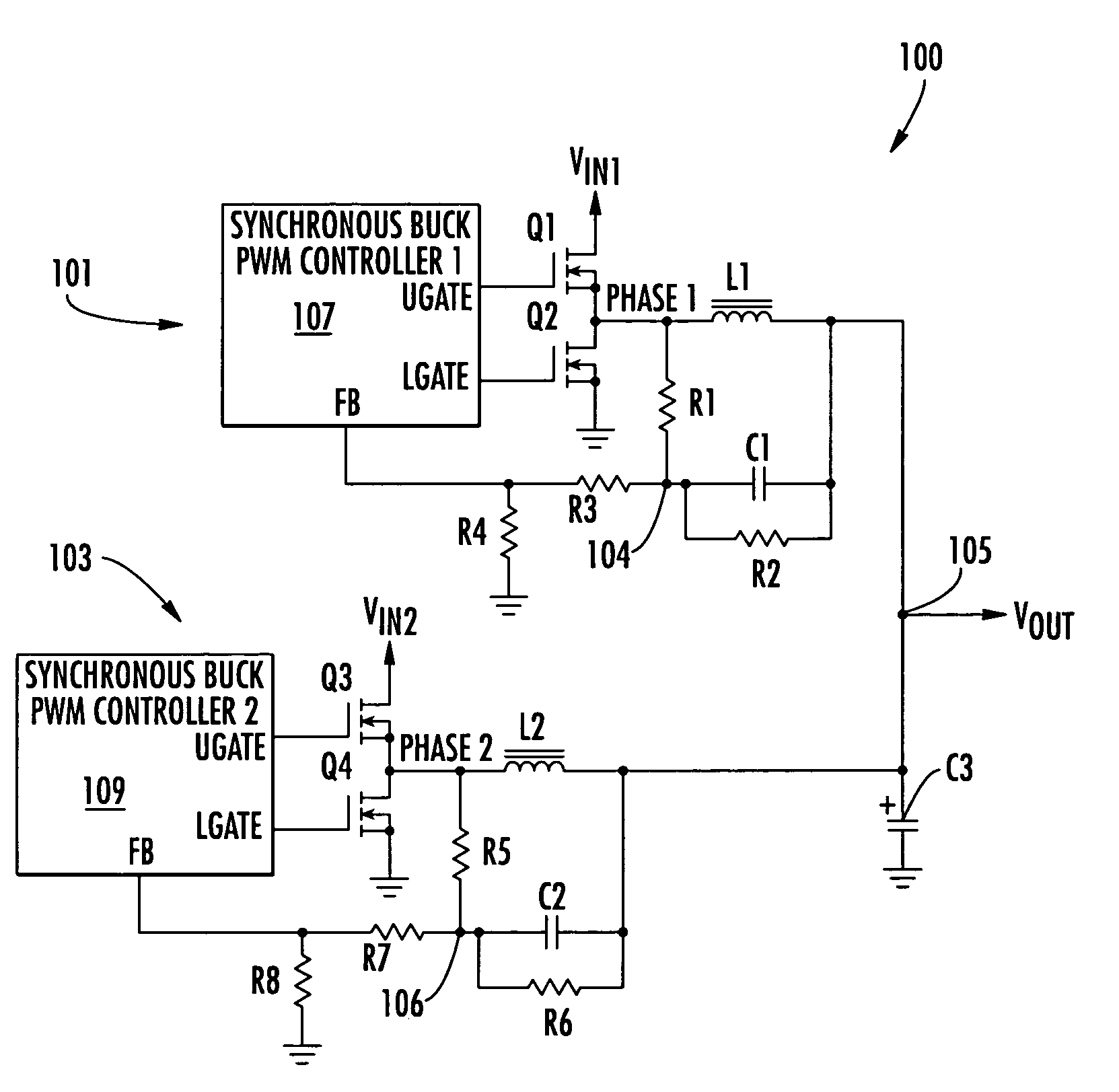
[0021]FIG. 1 is a schematic diagram of a regulator 100 implemented with a lossless output current sharing system according to an exemplary embodiment of the present invention. The regulator 100 includes a first buck converter 101 that down-converts from a first rail voltage VIN1 and a second buck converter 103 that down-converts from a second rail voltage VIN2 to generate a sin...


PUM


Abstract

A regulator with output current sharing including an output node and multiple converters. Each converter includes a PWM controller and switch circuit, an inductor, and an RC circuit. Each PWM controller and switch circuit receives a corresponding rail voltage and has a phase node and a regulation feedback input. Each inductor has a first end coupled to the output node and a second end coupled to a corresponding phase node. The RC circuit is coupled across the inductor and has an intermediate phase sense node coupled to a corresponding regulation feedback input. Each RC circuit may include an RC filter coupled across an inductor with an intermediate node and a feedback circuit coupled between the intermediate node and a regulation feedback input. The RC circuits may be configured to program a relative power distribution between the rail voltages to the shared output.

Description

CROSS-REFERENCE TO RELATED APPLICATIONS[0001]This application claims the benefit of U.S. Provisional Application No. 60 / 509,485 filed on Oct. 7, 2003, which is herein incorporated by reference for all intents and purposes.BACKGROUND OF THE INVENTION[0002]1. Field of the Invention[0003]The present invention relates to DC-DC power regulators, and more particularly to a system and method for output current sharing among multiple DC-DC PWM converters using droop control feedback.[0004]2. Description of the Related Art[0005]In many electronic devices and systems, including computer systems and peripherals, it is often desired to combine power from two or more power sources. Multiple power supplies are desired, for example, when a single source is insufficient or when redundancy is desired or otherwise required. A computer system typically has multiple rail voltages or voltage source levels, such as, for example, 12 Volts (V), 5 V, 3.3 V, etc., where each rail is capable of providing a pr...

Claims


Application Information

Patent Timeline
Patent Type & Authority Patents(United States)
IPC IPC(8): G05F1/40
CPCH02M3/1584H02M2001/0009H02M1/0009
Inventor MATTINGLY, DOUGLAS M.
Owner INTERSIL INC
Why Eureka
Try Eureka