Automatic coverage hole detection in computer network environments

a technology of automatic detection and computer network environment, applied in the field of wireless computer networks, can solve the problems of site surveys, time-consuming and expensive, and are responsive to periodic or subsequent changes

Active Publication Date: 2007-11-27
CISCO TECH INC
View PDF36 Cites 49 Cited by
  • Summary
  • Abstract
  • Description
  • Claims
  • Application Information

AI Technical Summary

Problems solved by technology

Such site surveys, however, are time consuming and expensive.
In addition, the analysis of the wireless network environment is performed with data gathered at a single point in time and, therefore, is not responsive to periodic or subsequent changes associated with the wireless network environment (such as new or intermittent sources of RF interference, etc.).
In addition, the test equipment may be located in areas where use of wireless client devices is infrequent or unimportant.

Method used


Image

  • Automatic coverage hole detection in computer network environments
  • Automatic coverage hole detection in computer network environments
  • Automatic coverage hole detection in computer network environments

Examples


Embodiment Construction

A. Operating Environment

[0013]For didactic purposes an embodiment of the present invention is described as operating in a WLAN environment as disclosed in U.S. application Ser. No. 10 / 155,938 incorporated by reference herein. As discussed below, however, the present invention can be implemented according to a vast array of embodiments, and can be applied to a variety of WLAN architectures.

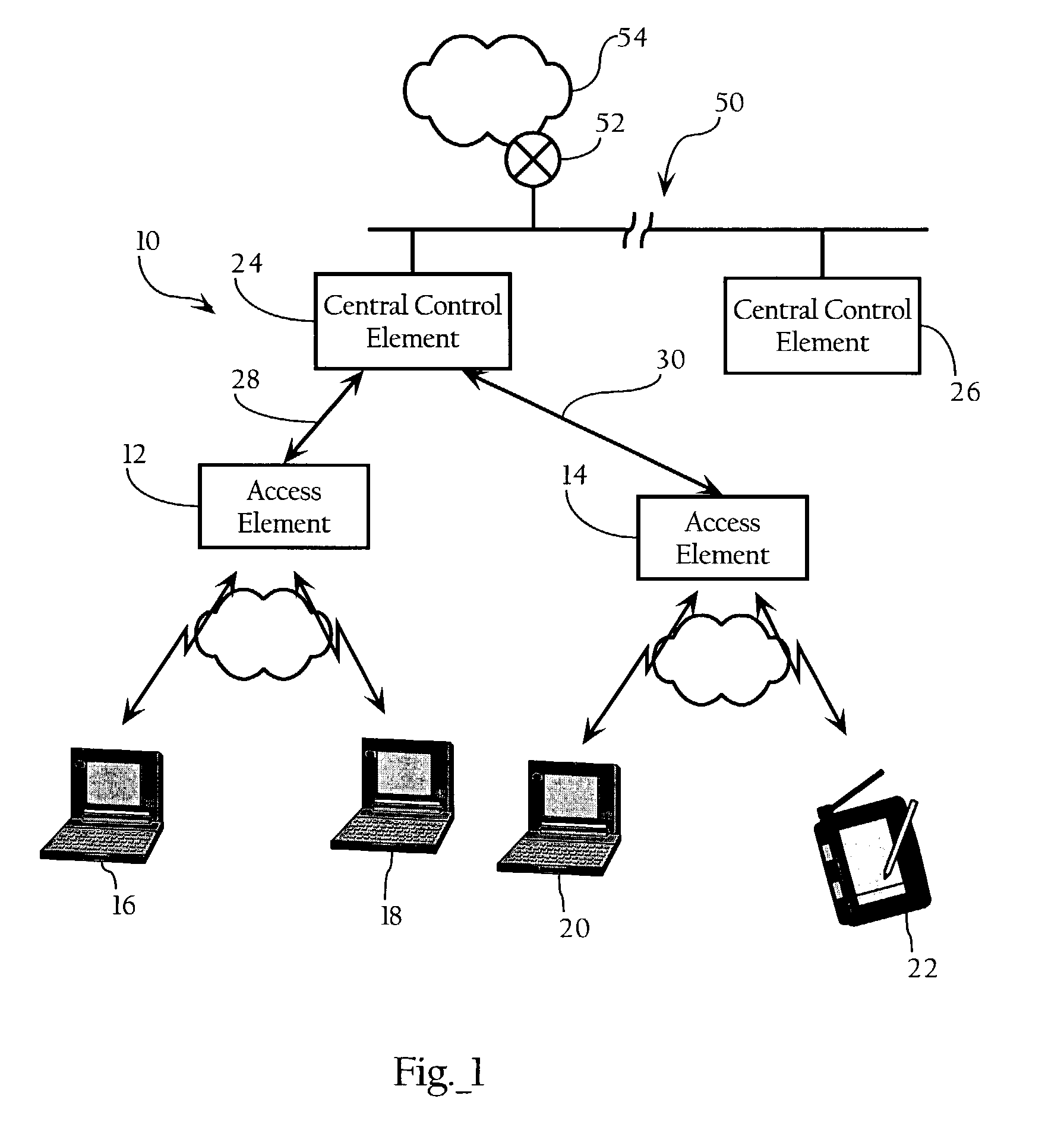
[0014]Referring to FIG. 1, there is shown block diagram of a wireless Local Area Network system 10 according to the invention. A specific embodiment of the invention includes the following elements: access elements 12, 14 for wireless communication with selected client remote elements 16, 18; 20, 22, central control elements 24, 26, and means for communication between the access elements and the central control elements, typically direct line access 28, 30, but potentially a wireless backbone, fiber or other reliable link. The wireless links between access elements 12, 14 and client remote elements...


PUM


Abstract

Methods, apparatuses and systems enabling real-time analysis of coverage and other performance attributes of distributed or networked systems, such as wireless computer network environments. In one embodiment, the present invention utilizes information obtained from monitoring wireless communications in a wireless network system from remote client elements to access elements in relation to at least one attribute, such as signal strength and signal-to-noise ratio (SNR). Although the present invention has application to a variety of wireless network architectures, in one embodiment, the present invention is implemented in a wireless Local Area Network (WLAN) system having a hierarchical architecture comprising a central control element associated with at least one access element. The access element encapsulates data packets received from remote client elements including protocol and other information (such as attributes of the detected signal associated with the data packets), and tunnels the encapsulated data packets to the central control element. The central control element maintains and analyzes the information contained in the packets to analyze the coverage of the wireless network environment.

Description

CROSS-REFERENCE TO RELATED APPLICATIONS[0001]This application makes reference to the following commonly owned U.S. patent applications and patents, which are incorporated herein by reference in their entirety for all purposes.[0002]U.S. patent application Ser. No. 10 / 155,938 in the name of Patrice R. Calhoun, Robert B. O'Hara, Jr. and Robert J. Friday, entitled “Method and System for Hierarchical Processing of Protocol Information in a Wireless LAN.”FIELD OF THE INVENTION[0003]The present invention relates to wireless computer networks and, more particularly, to methods, apparatuses and systems facilitating analysis of coverage associated with wireless computer network deployments.BACKGROUND OF THE INVENTION[0004]The market adoption of wireless LAN (WLAN) technology has exploded, as users from a wide range of backgrounds and vertical industries have brought this technology into their homes, into their offices, and increasingly into the public air space. This inflection point has hig...

Claims


Application Information

Patent Timeline
Patent Type & Authority Patents(United States)
IPC IPC(8): H04Q7/24H04W16/00H04W24/08
CPCH04W24/08H04W16/00
Inventor DIETRICH, PAUL F.FRIDAY, ROBERT J.O'HARA, JR., ROBERT B.
Owner CISCO TECH INC
Why Eureka
Try Eureka