Pulsed plasma thruster and method of making

a plasma thruster and plasma technology, applied in the field of pulsed plasma thrusters, can solve the problems of not providing the capability to operate a thruster using common liquid or melted solid substances, springs or other mechanical devices can be very difficult or impractical to use on very small scales, and none of the references teach compact or micro-pp

Inactive Publication Date: 2007-12-04
THE JOHN HOPKINS UNIV SCHOOL OF MEDICINE
View PDF24 Cites 20 Cited by
  • Summary
  • Abstract
  • Description
  • Claims
  • Application Information

AI Technical Summary

Problems solved by technology

This design does not provide the capability to operate a thruster using common liquid or melted solid substances as propellants.
While the related art generally teaches different PPT designs, none of the references teach a compact or micro-PPT that is susceptible to easy and rapid manufacture, includes no moving parts and is easy to deploy and integrate into existing and future satellite architecture.
These springs or other mechanical devices can be very difficult or impractical to use on very small scales.

Method used


Image

  • Pulsed plasma thruster and method of making
  • Pulsed plasma thruster and method of making
  • Pulsed plasma thruster and method of making

Examples


Embodiment Construction

)

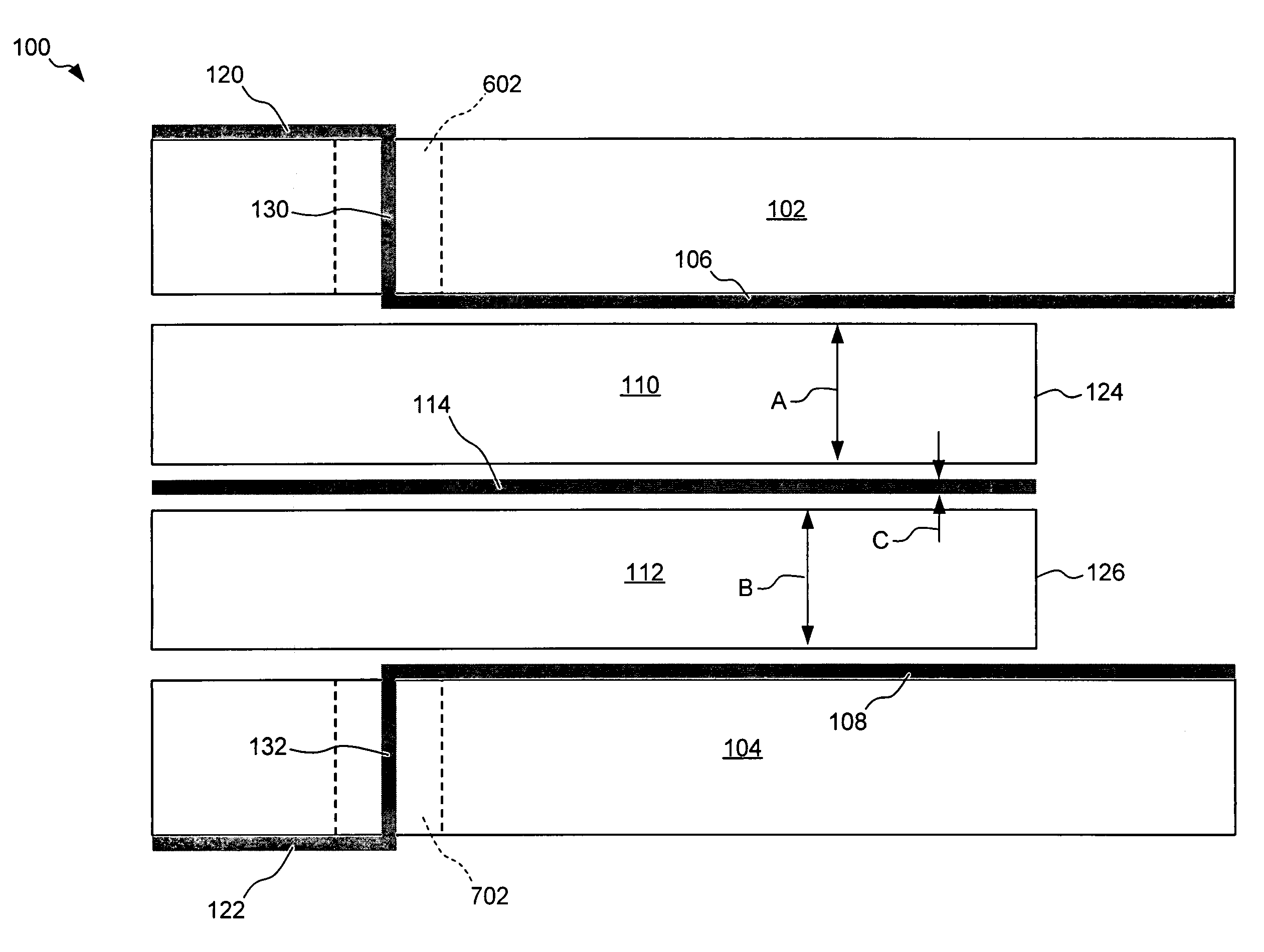
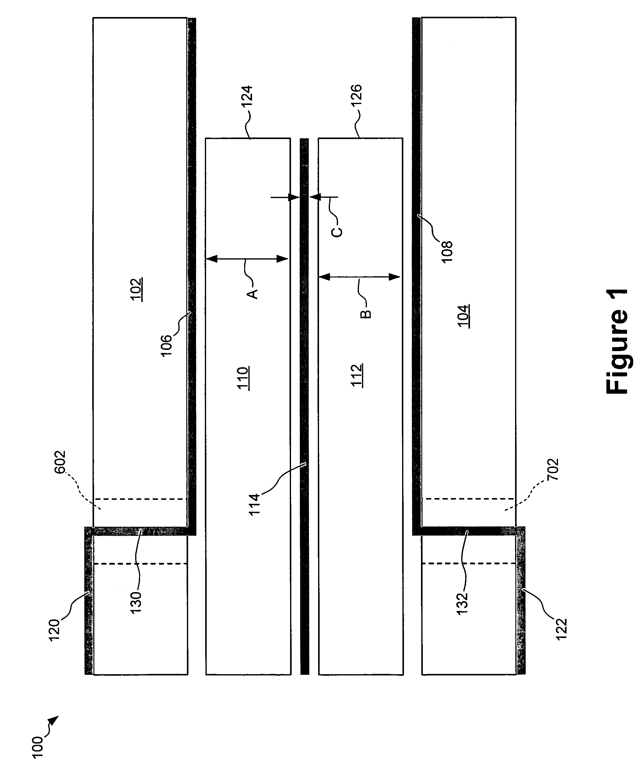
[0102]FIG. 1 is a cross-sectional schematic diagram of a preferred embodiment of Pulsed Plasma Thruster (PPT) 100. PPT 100 includes a housing, and in the embodiment shown in FIG. 1, the housing is comprised of first substrate 102 and second substrate 104. Preferably, one or more layers of materials are disposed between the first and second substrates 102 and 104, respectively, to form PPT 100. In a preferred embodiment, a first conductive layer 106 is disposed on first substrate 102 and a second conductive layer 108 is disposed on second substrate 104.

[0103]Preferably, a first fuel layer 110, an igniter device 114 and a second fuel layer 112 are disposed between first conductive layer 106 and second conductive layer 108. In a preferred embodiment, first fuel layer 110 is disposed proximate to first conductive layer 106 and second fuel layer 112 is disposed proximate to second conductive layer 108. Also, igniter device 114 is preferably disposed between first fuel layer 110 and seco...


PUM


Abstract

A pulsed plasma thruster (PPT) and a method of making the pulsed plasma thruster are disclosed. The PPT includes no moving parts and is able to achieve a small size. The PPT is also designed to facilitate easy and rapid manufacture. The process for making the PPT uses known techniques for making printed circuit board devices. Another PPT also has no moving parts and uses a liquid fuel that is progressively advanced by capillary action.

Description

CROSS REFERENCE TO RELATED APPLICATIONS[0001]This application claims the benefit of U.S. Provisional Patent Application No. 60 / 511,771, filed on Oct. 16,2003. This Provisional Patent Application is hereby incorporated by reference in its entirety.BACKGROUND OF THE INVENTION[0002]1. Field of the Invention[0003]This invention relates to a Pulsed Plasma Thruster (“PPT”) and a method for making a PPT.[0004]2. Related Art[0005]As satellites become smaller and as larger satellites require highly precise motion control, a need arises for smaller thrusters. PPTs have been proposed for use in these kinds of applications and many different PPT designs have been attempted.[0006]Spanjers (U.S. Pat. No. 6,269,629) discloses a micro-PPT that uses a coaxial cable configuration. Spanjers uses the insulation of the cable or the spacer, made of a copolymer, disposed between a cylindrical outer conductor and an inner conductor as the fuel.[0007]Spanjers (U.S. Pat. No. 6,153,976) discloses a PPT that r...

Claims


Application Information

Patent Timeline
Patent Type & Authority Patents(United States)
IPC IPC(8): F03H1/00H01J7/24B64G1/40
CPCF03H1/0087B64G1/405F03H1/00B64G1/40
Inventor LAND, III, H. BRUCESIMON, DANIEL H.RICE, THAREN
Owner THE JOHN HOPKINS UNIV SCHOOL OF MEDICINE
Why Eureka
Try Eureka