Thermal printer and method for correcting the energizing time data for heating elements in the thermal printer

a technology of thermal printer and energizing time data, which is applied in the field of image forming apparatus, can solve the problems of excessive cooling of thermal head, and possibility of reducing the density of the next line, so as to prevent excessive temperature reduction of thermal head

Inactive Publication Date: 2007-12-04
FUNAI ELECTRIC CO LTD
View PDF9 Cites 6 Cited by
  • Summary
  • Abstract
  • Description
  • Claims
  • Application Information

AI Technical Summary

Benefits of technology

[0016]The present invention has been made to solve the above-described problems, and an object thereof is to provide a thermal printer (image forming apparatus) in which excessive temperature reduction of a thermal head is prevented and a method for controlling the energizing time for the thermal head (heating elements).
[0030]In the thermal printer according to the present invention, it is possible to reduce the effect of remaining heat energy by delaying the start of energization in the pre-correction energizing time data for a target dot (i.e. by shortening the energizing time). Meanwhile, it is possible to prevent a situation where the temperature of heating elements is reduced excessively when printing dots in the next line by delaying the end of energization in the pre-correction energizing time data (i.e. by adding energizing time).

Problems solved by technology

Therefore, if remaining heat energy (corresponding especially to the adjacent heat effect) may be subtracted excessively from the energy applied for the normal time, the temperature of the thermal head is to be reduced too much when printing the next line (refer to FIG. 15), resulting in a possibility of reducing the density of the next line.
Hei 6-255141, there is a possibility that the thermal head may be cooled excessively.
In this case, the temperature of the thermal head is to be reduced too much when printing the next line (refer to FIG. 15), resulting in a possibility of reducing the density of the next line, as is the case with the foregoing example.

Method used


Image

  • Thermal printer and method for correcting the energizing time data for heating elements in the thermal printer
  • Thermal printer and method for correcting the energizing time data for heating elements in the thermal printer
  • Thermal printer and method for correcting the energizing time data for heating elements in the thermal printer

Examples


first embodiment

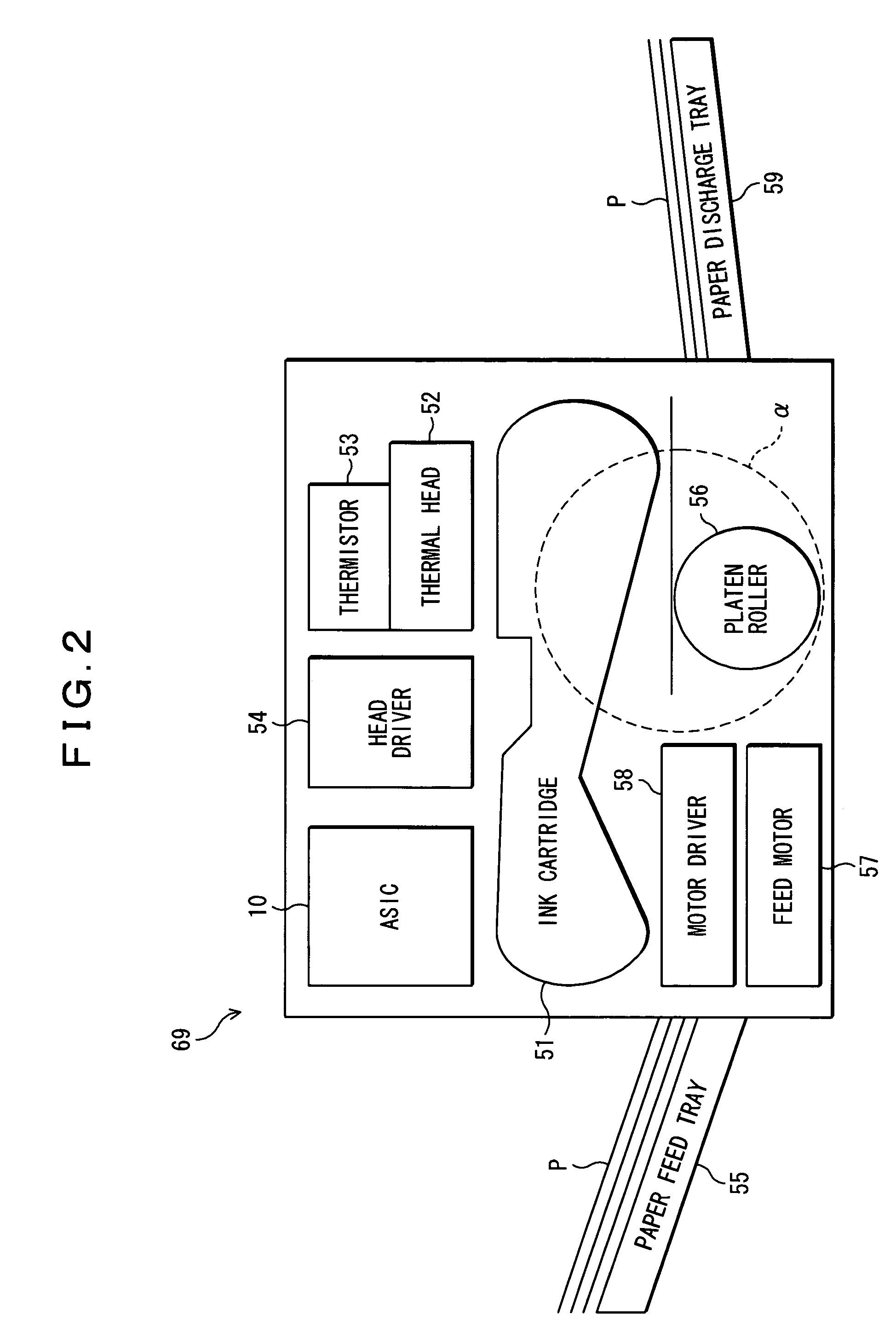
[0047]One embodiment of the present invention will hereinafter be described with reference to the accompanying drawings. FIG. 2 is a schematic block diagram of a thermal transfer type dye sublimation thermal printer (image forming apparatus) 69 according to the present invention, and FIG. 3 is an enlarged schematic block diagram of the part “□” in FIG. 2. Then, FIG. 4 is a view showing the positional relationship between the direction in which a sheet P flows (feed direction in a printing operation) and a thermal head 52, and FIG. 5 shows a cross-sectional shape (cross-sectional view along the line U-U′) of each heating element 52a in FIG. 4

[1. Schematic Configuration of the Thermal Printer]

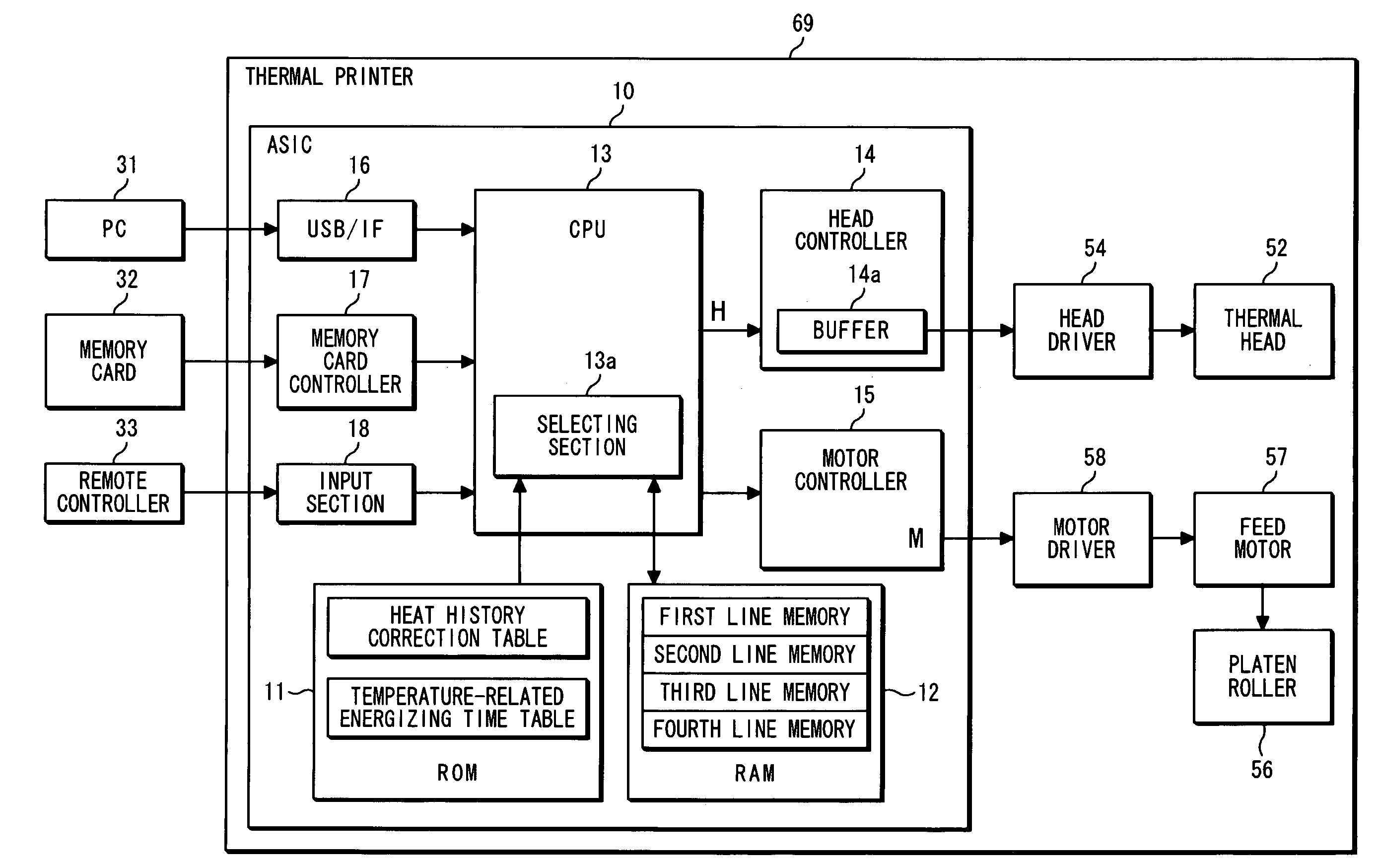
[0048]The thermal printer 69 according to the present invention and shown in FIGS. 2 and 3 is arranged to include at least an ink cartridge 51, a thermal head 52, a thermistor 53, a head driver 54, a paper feed tray 55, a platen roller 56, a feed motor 57, a motor driver 58, a paper discharge tra...


PUM


Abstract

A thermal printer comprises: a ROM 11 for storing a heat history correction table; a RAM 12 for storing the density-related energizing time data for the first and second preceding lines printed immediately before the current line to be printed and the density-related energizing time data before a correction for the current line to be printed which includes a target dot T; and a control section for comparing the density-related energizing time data for the first and second preceding lines and the density-related energizing time data before a correction for both adjacent dots T1 and T2 of the target dot T with the density-related energizing time data before a correction for the target dot T to select reference data, and further for performing a corrective operation for the pre-correction energizing time data for the target dot T using thus selected reference data to calculate energizing time data for the target dot T to be printed, whereby it is possible to prevent the temperature of a thermal head from being reduced excessively.

Description

BACKGROUND OF THE INVENTION[0001]1. Field of the Invention[0002]The present invention relates to an image forming apparatus such as a thermal printer that uses a thermal head and to a method for correcting the energizing time data for heating elements in the thermal printer.[0003]2. Description of the Prior Art[0004]There have recently been developed image forming apparatuses adapted to print printing data (YMC data) obtained by converting and expanding image data (RGB data) from a digital still camera (digital camera). Since YMC data is composed of tone data, it is suitable to use an image forming apparatus having high tone reproducibility. Hence, there have been developed thermal transfer type image forming apparatuses (e.g. thermal printers) that are considered to have higher tone reproducibility relative to inkjet type image forming apparatuses.[0005]In general, inkjet type image forming apparatuses have only two alternative values whether or not to fire an ink droplet onto one ...

Claims


Application Information

Patent Timeline
Patent Type & Authority Patents(United States)
IPC IPC(8): B41J2/36
CPCB41J2/365
Inventor NAITO, TADAHIRONODA, YUTAKA
Owner FUNAI ELECTRIC CO LTD
Why Eureka
Try Eureka