Reversible weapon telescope mount

a telescope mount and weapon technology, applied in the field of weapon telescope mounts, can solve the problems of lack of universal scope mounts in the prior art, deficiencies that need to be overcome, and common difficulty in relating to the height of the scope moun

Active Publication Date: 2007-12-11
FROST MICHAEL
View PDF5 Cites 18 Cited by
  • Summary
  • Abstract
  • Description
  • Claims
  • Application Information

AI Technical Summary

Benefits of technology

[0015]Employment of the novel telescope mount of the present invention provides for a low profile mount. In particular, a bottom surface of the mount top support rests along a top surface of the gun receiver. Accordingly, the telescope mount of the present invention becomes a part of the gun to which it is attached. Removal of the telescope does not require removal of the novel mount of the invention. When the telescope is removed, the mount remains on the gun and does not affect the firing of the gun or block the integral OEM sighting device of the gun. Accordingly, a shooter can remove his scope, stow it away and continue to fire his weapon without removing the mount and without his OEM sighting device being interfered. My scope mount is not meant to be a quick release mechanism, but instead a fixed and / or integral part of the gun.

Problems solved by technology

Hence, the lack of any universal scope mount existing in the prior art.
Scope mounts of the prior art, regardless of their intended mount, have deficiencies that need to be overcome.
The most common difficultly relates to the height of the scope mount.
Further, a soldier does not want to make himself visible or give his position away (especially in case of a sniper), nor does he want to make his gun bulky or awkward to handle.
Accordingly, he does not want a scope mount that has a high profile, a very typical problem in the prior art.
It is intended to be a quick release device wherein precise accuracy is not a factor (clearly not suitable for a sniper).
High profile devices greatly alter the center of gravity of the weapon and make the weapon more awkward to handle due to the displacing of the weight of the scope to an exaggerated height above the receiver of the weapon.
Further, these prior art high profile devices interfere with the OEM sighting device on the gun.
However, these high profile mount devices do allow a shooter to quickly remove the scope in its entirety and return the gun to its natural, stripped-down state, a condition that many leisurely users find enticing.
However, soldiers preparing for battle or a sniper headed out on a multi-day mission are not concerned with quickly mounting their scopes.
And the high profile, quick releasable scope mounts lack the functional ability that the soldier needs.

Method used


Image

  • Reversible weapon telescope mount
  • Reversible weapon telescope mount
  • Reversible weapon telescope mount

Examples


Embodiment Construction

, contained herein below, may be better understood when accompanied by a brief description of the drawings, wherein:

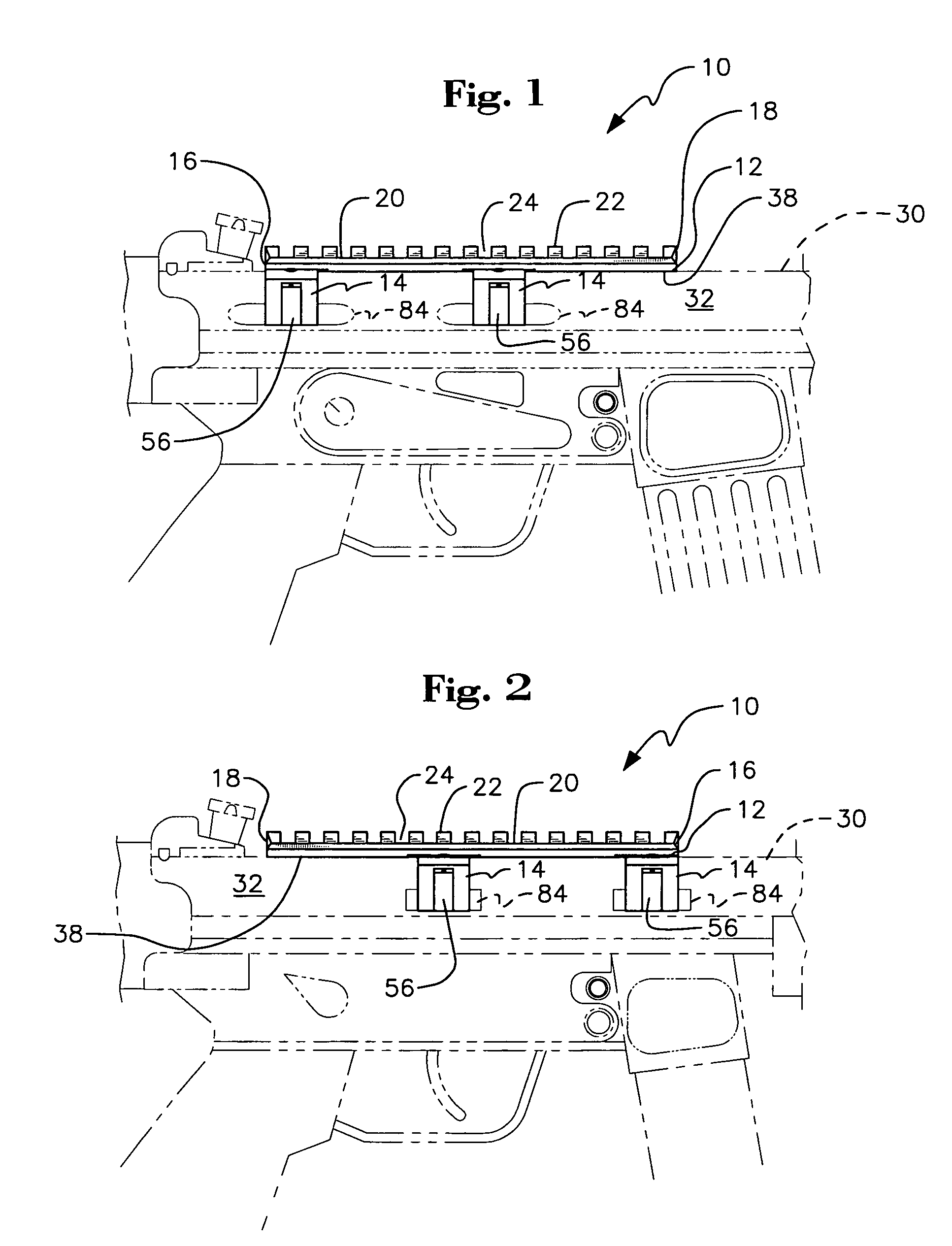
[0017]FIG. 1 is a side plan view of a reversible weapon scope mount of the present invention;

[0018]FIG. 2 is a side plan view of the reversible weapon scope mount of the present invention employed in a direction opposite to that as shown in FIG. 1;

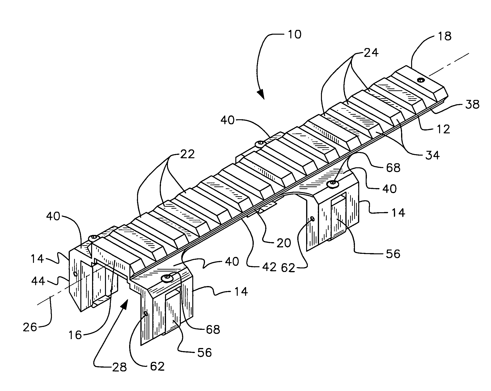
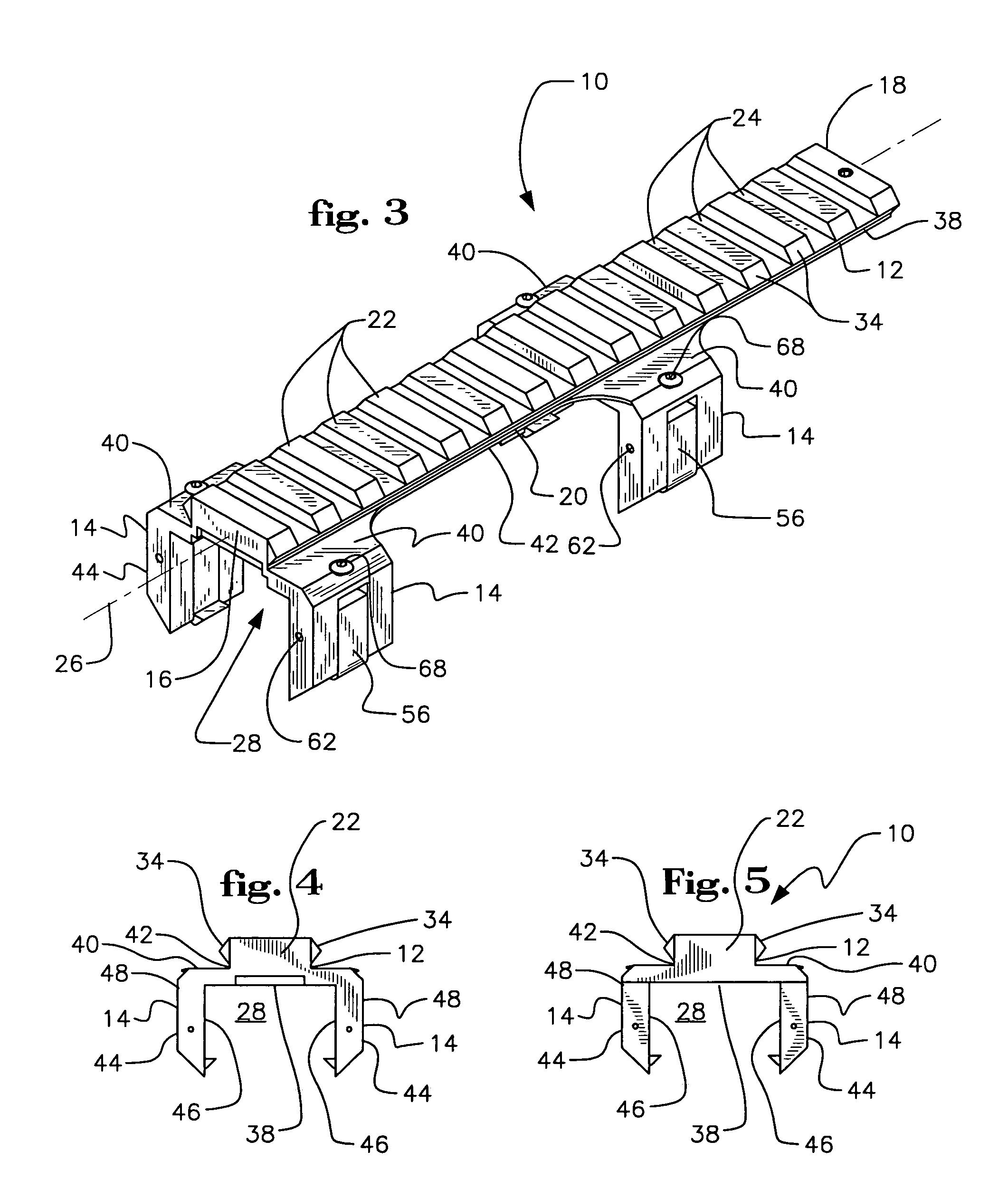
[0019]FIG. 3 is a perspective view of the novel reversible scope mount;

[0020]FIG. 4 is a back side view of the reversible scope mount;

[0021]FIG. 5 is a front side view thereof;

[0022]FIG. 6 is a side plan view of the reversible scope mount of the present invention illustrated when not employed on a weapon;

[0023]FIG. 7 is a cross-sectional view of the invention taken along lines 7-7 of FIG. 6;

[0024]FIG. 8 is another cross-sectional view of the present invention, but taken along lines 8-8 of FIG. 6;

[0025]FIG. 9 is a partial perspective view of the reversible weapon scope mount of the present invention illustrating, in detail, on...


PUM


Abstract

A low profile, reversible weapon telescope mount is provided. The mount has a longitudinal planar top support having a series of ridges and recesses disposed thereupon in an alternating and parallel orientation to that of a central axis of the support. Attached to opposed peripheral side edges of the support are four downwardly depending legs. The support and legs form a channel of the scope mount that surrounds a top end of a weapon receiver, such as a rifle, such that a bottom surface of the top planar support rests upon a top surface of the receiver. Each leg has a movable guide finger supported in a vertical channel formed in each leg. Each guide finger has an inwardly extending ledge member for grabbing outwardly extending flanges of the rifle receiver. The finger is guided up and down by an pin inserted through the leg and finger when a screw, acting upon the finger is tightened or loosened. The mount can be reversed so that its front end is closer to the head of the user of the weapon while still permitting a telescope to be mounted thereupon.

Description

BACKGROUND OF THE INVENTION[0001]1. Field of Invention[0002]The present invention relates to weapon telescope mounts. More particularly, this invention relates to a reversible weapon telescope mount for use with a variety of different models of rifles, submachine guns and machine guns and whose use does not necessitate the employment of other attachment elements.[0003]2. Description of the Prior Art[0004]Weapon telescope mounts, and those specifically used for rifles, submachine guns and machine guns, are well known in the prior art. Hunters, marksman as well as soldiers throughout the world use telescopes (“scopes”) regularly as part of their rifle, submachine gun or machine gun system. A weapon telescope assists a shooter by zeroing in the aim of the weapon on a target which is at a distance outside the operable, visual range of the human eye. Usually, a set of cross hairs or an electronic pin-pointing mechanism is enclosed within the telescope which allows the shooter to place a ...

Claims


Application Information

Patent Timeline
Patent Type & Authority Patents(United States)
IPC IPC(8): F41G1/16
CPCF41G11/003
Inventor FROST, MICHAEL
Owner FROST MICHAEL
Why Eureka
Try Eureka