Device for determining at least one parameter of a medium flowing in a line having diversion surface

a technology of diversion surface and device, which is applied in the direction of machines/engines, electrical control, instruments, etc., can solve the problem of no longer being separated from the sidewalls of the bypass part, and achieve the effect of preventing the separation of the flow

Active Publication Date: 2007-12-11
ROBERT BOSCH GMBH
View PDF13 Cites 27 Cited by
  • Summary
  • Abstract
  • Description
  • Claims
  • Application Information

AI Technical Summary

Benefits of technology

[0004]It is an object of the invention to determine at least one parameter of a medium flowing in a line. It is a further object of the invention to largely prevent separation of the flow with large areas of separated flow at the sidewalls of the bypass part.

Problems solved by technology

As a result, even at low flow speeds in the line component the boundary layer becomes turbulent as far upstream as the area near the diversion surface and thus no longer separates from the sidewalls of the bypass part.

Method used


Image

  • Device for determining at least one parameter of a medium flowing in a line having diversion surface
  • Device for determining at least one parameter of a medium flowing in a line having diversion surface
  • Device for determining at least one parameter of a medium flowing in a line having diversion surface

Examples


Embodiment Construction

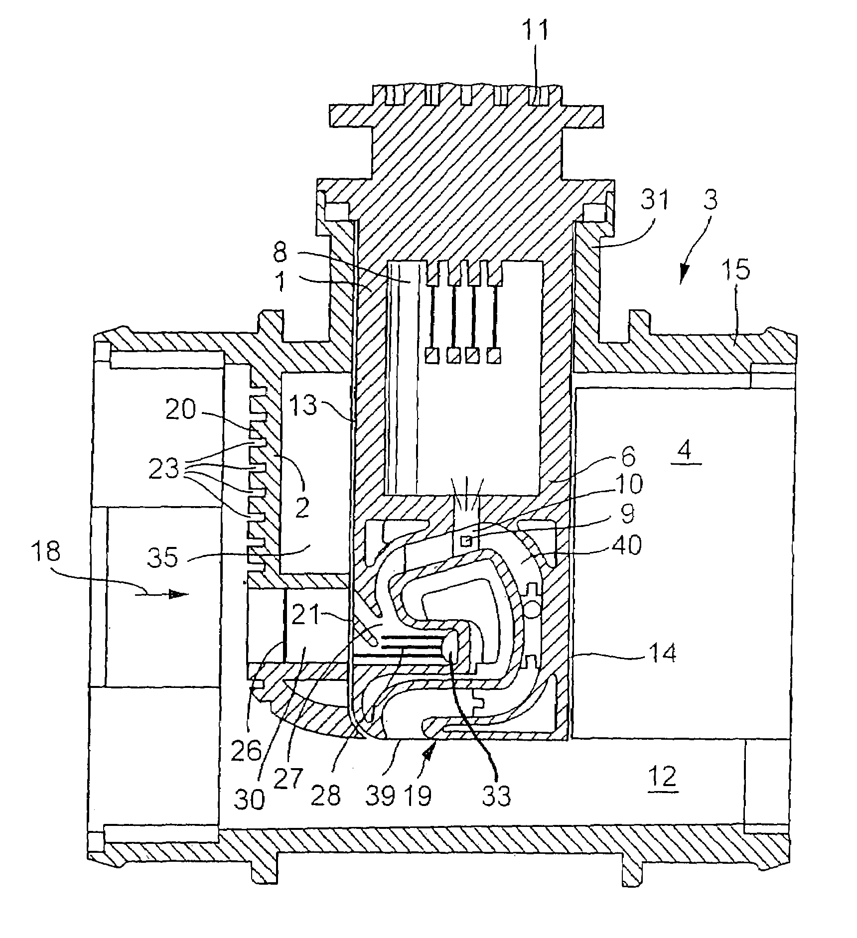
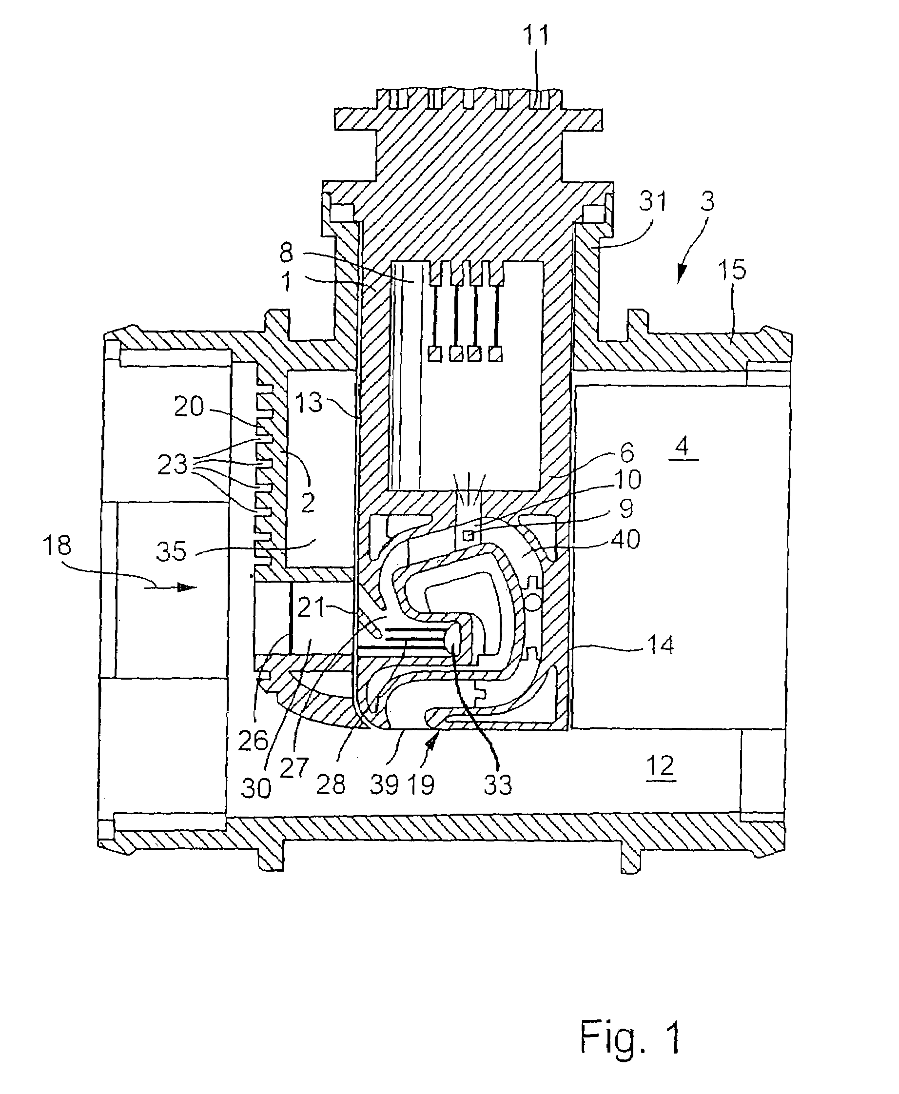
[0018]In a particularly simple manner the flow diversion element may have an elliptically curved diversion surface. Herein, the small semi-axis of the elliptically curved diversion surface is equal to half the distance between the two sidewalls of the bypass part. The large semi-axis of the elliptically curved diversion surface is at least twice the length of the small semi-axis.

[0019]The turbulence-generating structure may be formed in a very simple manner via at least one wire applied to the diversion surface or situated in the immediate proximity thereof. The wire may, for example, have a plurality of alternating curves and a serrated shape having a large number of serrations.

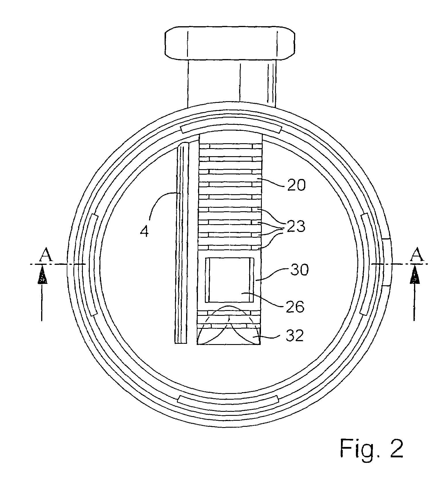
[0020]An exemplary embodiment in which the turbulence-generating structure is formed via a plurality of slits created in the diversion surface, each of which is in a plane perpendicular to the sidewalls of the bypass part and parallel to the main flow direction, is particularly advantageous. The flow of medi...


PUM


Abstract

A device for determining at least one parameter of a medium flowing in a line, in particular for determining the air mass flow rate in the intake manifold of an internal combustion engine, which include a line component 3 and a sensor device 1 having a bypass part 6, are known. To prevent separation of the flow at the sidewalls of the bypass part, it is provided that a flow diversion element 2 be positioned in the line component 3 upstream from the bypass part 6 with respect to the main flow direction 18 and have at least one diversion surface 20 facing the main flow direction 18, which, starting from an apex line 25 located at a distance from the bypass part 6, curves evenly on both sides toward the two sidewalls 16, 17 so that the ends 38 of the diversion surface 20 facing away from the apex line are aligned with the sidewalls 16, 17.

Description

FIELD OF THE INVENTION[0001]The present invention relates to a device for determining at least one parameter of a medium flowing in a line.DESCRIPTION OF RELATED ART[0002]A device of this kind is known for example from DE 101 35 142 A1 and is used for example in the air intake manifold of an internal combustion engine to determine the air mass flow rate through a line to the internal combustion engine. A section of a sensor device having a bypass part is inserted through an insertion opening into the line component. The bypass part has a channel structure having an inlet area, from which a measuring channel, in which the measuring element is provided, branches off. Furthermore, the intake area has a removal area having at least one removal opening, which opens into the line through-channel at least one sidewall of the bypass part. The purpose of the removal zone is to remove liquid and / or solid particles from the channel structure and thus keep them from penetrating the measuring ch...

Claims


Application Information

Patent Timeline
Patent Type & Authority Patents(United States)
IPC IPC(8): G01F1/68G01F1/684G01F5/00G01F15/12
CPCG01F1/6842G01F15/12G01F5/00G01F1/684G01F1/72F02D41/18
Inventor BEYRICH, HANSKONZELMANN, UWEGMELIN, CHRISTOPHHENNIG, OLIVER
Owner ROBERT BOSCH GMBH
Why Eureka
Try Eureka