Volumetric control apparatus for fluid dispensing

a fluid dispensing and fluid technology, applied in process and machine control, instruments, data switching networks, etc., can solve the problems of system control of initiation and termination of fluid flow, ineffective description of apparatus, and inability to allow users to select a specific volume to be dispensed

Active Publication Date: 2007-12-11
UNIV OF SOUTH FLORIDA RES FOUND
View PDF15 Cites 18 Cited by
  • Summary
  • Abstract
  • Description
  • Claims
  • Application Information

AI Technical Summary

Benefits of technology

[0007]The fluid exists within the conduit of the apparatus under pressure. The operating pressure of the system maintains accuracy over a wide pressure range, thereby providing accuracy stability under pressure variations, inclusive of any typical water delivery pressures. In accordance a particular embodiment of the present invention, the pressure of the fluid under pressure is between about 25 psi and about 60 psi. This range of pressure is typical of a domestic water source. In an additional embodiment, the present invention further includes a pressure regulator positioned inline with the conduit. If the fluid pressure is not within the preferred range, the pressure regulator serves to regulate the fluid under pressure reaching the flow meter to between about 25 psi and about 60 psi.
[0015]Accordingly, the present invention provides a volumetric control apparatus for fluid dispensing that provides benefits over other systems known in the art. The present invention eliminates the need for peripheral measuring devices by allowing the user to select and dispense a controlled volume of fluid. The present invention allows the user to select a specific volume and the apparatus controls the fluid initiation and termination to dispense the user selected volume as specified.

Problems solved by technology

However, the systems known in the art do not describe an apparatus effective in supplying a preset quantity of liquid, as specified by a user, from a source of fluid under pressure.
Additionally, while prior art systems are known for metering the flow of fluid from a source, these systems do not allow the user to select a specific volume to be dispensed.
By contrast, the flow meter systems known in the art present the flow measurement to the user, but the systems do not control the initiation and termination of the fluid flow to dispense the specific volume selected by the user.

Method used


Image

  • Volumetric control apparatus for fluid dispensing
  • Volumetric control apparatus for fluid dispensing
  • Volumetric control apparatus for fluid dispensing

Examples


Embodiment Construction

[0021]In the following detailed description of the preferred embodiments, reference is made to the accompanying drawings, which form a part thereof, and within which are shown by way of illustration specific embodiments by which the invention may be practiced. It is to be understood that other embodiments may be utilized and structural changes may be made without departing from the scope of the invention.

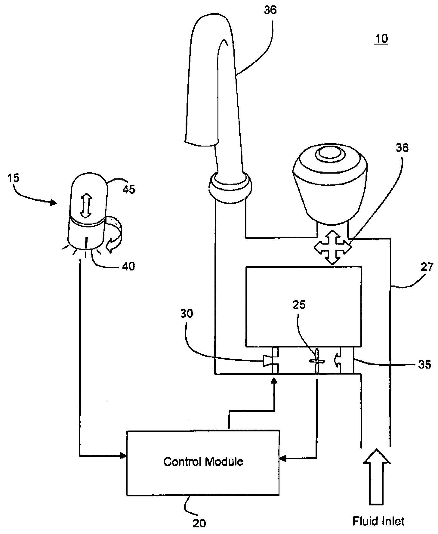
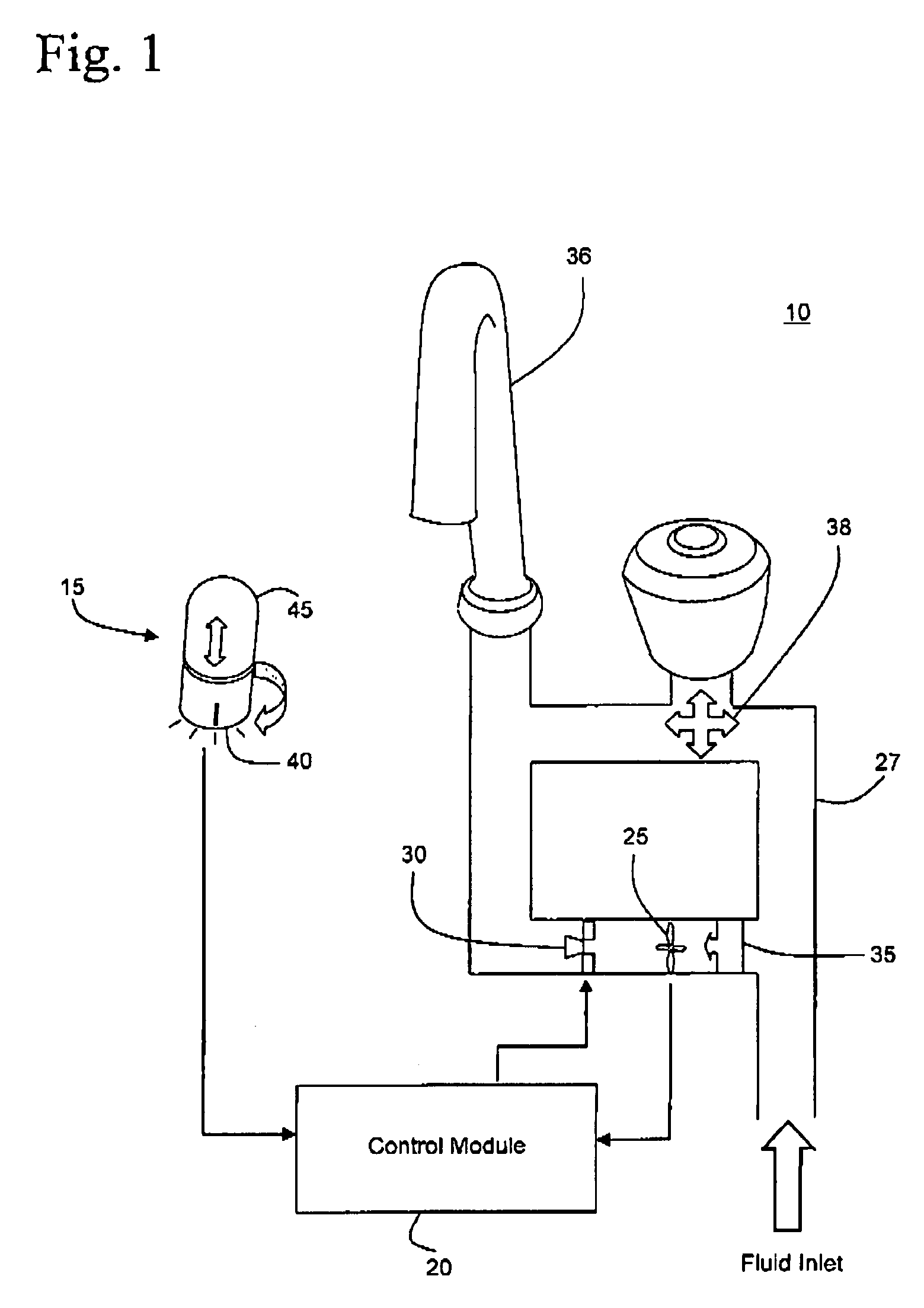
[0022]With reference to FIG. 1, in an overall view, the volumetric control apparatus for fluid dispensing 10 in accordance with the present invention includes a user control switch assembly 15, a control module 20, a water flow meter 25, and a solenoid water valve 30, wherein the water flow meter 25 and the solenoid water valve 30 are positioned within a conduit 27 for holding the water under pressure. Operation of the volumetric control apparatus of the present invention utilizes a 120 volt 50 / 60 Hz AC or DC battery supply and a water source under pressure. Water flow pressure resu...


PUM

PropertyMeasurementUnit
pressureaaaaaaaaaa
pressureaaaaaaaaaa
volumeaaaaaaaaaa

Abstract

The present invention provides an apparatus for dispensing fluid in preselected volumetric quantities. The apparatus comprises a valve positioned inline with a conduit holding fluid under pressure, a flow meter positioned inline with the conduit, a control unit communicatively coupled to the valve and flow meter, the control unit adapted to open and close the valve and detect data from the flow meter associated with the volume of fluid passing through the conduit, a units select switch having a plurality of preselected settings associated with a plurality of volumetric units, the units select switch communicatively coupled to the control unit, and an incrementing switch communicatively coupled to the control unit, whereby the control unit opens the valve responsive to activation of the incrementing switch thereby permitting fluid flow through the conduit until the control unit closes the valve responsive to the flow meter indicating a volume of fluid passed through the conduit substantially equal to a volumetric unit selected on the units select switch.

Description

CROSS REFERENCE TO RELATED APPLICATIONS[0001]This application is a continuation of International Patent Application No. PCT / US2004 / 012361, filed on Apr. 22, 2004, which claims the benefit of U. S. Provisional Patent Application Ser. No. 60 / 320,131 filed Apr. 22, 2003.BACKGROUND OF THE INVENTION[0002]Conventional methods for measuring volumes of liquid require a collection of measuring implements, such as measuring cups and spoons. These measuring implements known in the art are fabricated to measure and deliver a preset volume of liquid as determined by each individual measuring implement. It is desirable to eliminate the need for measuring implements, and to instead provide a preset quantity of liquid directly from the source of the liquid. As an example, it is desirable to have the ability to supply a volume of water equal to a specific measurement directly from a kitchen faucet. Accordingly, it would be possible to supply a quantity equal to one cup, or 8 ounces, directly from th...

Claims


Application Information

Patent Timeline
Patent Type & Authority Patents(United States)
IPC IPC(8): G01F11/00E03C1/05G01F1/10G01F15/00G01NG05D7/06
CPCG01F1/103G05D7/0635G01F15/003G01F13/008Y10T137/7761
Inventor BEACHY, TIMOTHY C
Owner UNIV OF SOUTH FLORIDA RES FOUND
Why Eureka
Try Eureka