Smart card and method for its production

a technology of smart cards and production methods, applied in the field of smart cards, can solve the problems of limited data transmission, contactless smart cards only qualify for transactions with relatively short duration, and transmitted data may be intercepted without the cardholder realizing, so as to prolong the communication distance of smart cards, facilitate card holder's experience, and facilitate the effect of longer transactions

Inactive Publication Date: 2007-12-11
INT BUSINESS MASCH CORP
View PDF6 Cites 57 Cited by
  • Summary
  • Abstract
  • Description
  • Claims
  • Application Information

AI Technical Summary

Benefits of technology

[0012]Starting from this, the object of the present invention is to provide means for extending the communication distance of a smart card to, thus, allow longer transactions between the smart card and a card acceptance device. This will result in a more convenient experience for the card holder, once, because the smart card will start working earlier when approaching the card acceptance device—the cardholder will perceive this as a shorter transaction time—and, twice, the smart card will work longer when moving away from the card acceptance device—the cardholder will perceive this as a longer communication distance and a more fault tolerant system. In any case, the longer the transaction interval is the more data can be transmitted between the smart card and the card acceptance device.BRIEF SUMMARY OF THE INVENTION
[0015]The idea of the present invention is to use the effect of a core inside of a coil solenoid. Such a core increases the distance in which the smart card can be read and is able to communicate with an appropriate card acceptance device.
[0016]Substantial for the present invention is, that the metal core is positioned in the magnetic field of the antenna. This can be achieved, e.g., by positioning the metal core on one of the main surfaces of the card body. In a very advantageous embodiment of the present invention the metal core is embedded in the card body together with the antenna and the chip.

Problems solved by technology

Despite the advantages of contactless smart cards, these cards have their own drawbacks.
As the card may move out of range very quickly, only limited data can be transmitted and the transmitted data may be intercepted without the cardholder realizing it.
That is why contactless smart cards only qualify for transactions with relatively short duration.
On contactless smart cards that carry two or more chips using the same antenna (e.g. a Mifare and a Legic chip) or that have two or more antennas (e.g. a JavaCard dual interface chip and a Legic chip), this problem is even worse.
This problem applies to data communication, too.

Method used


Image

  • Smart card and method for its production
  • Smart card and method for its production
  • Smart card and method for its production

Examples


Embodiment Construction

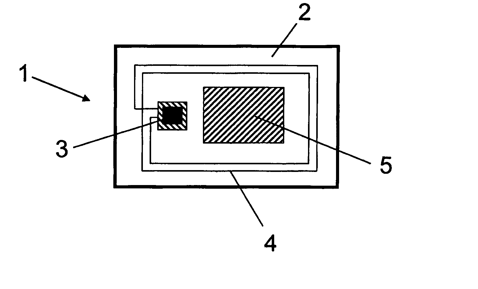
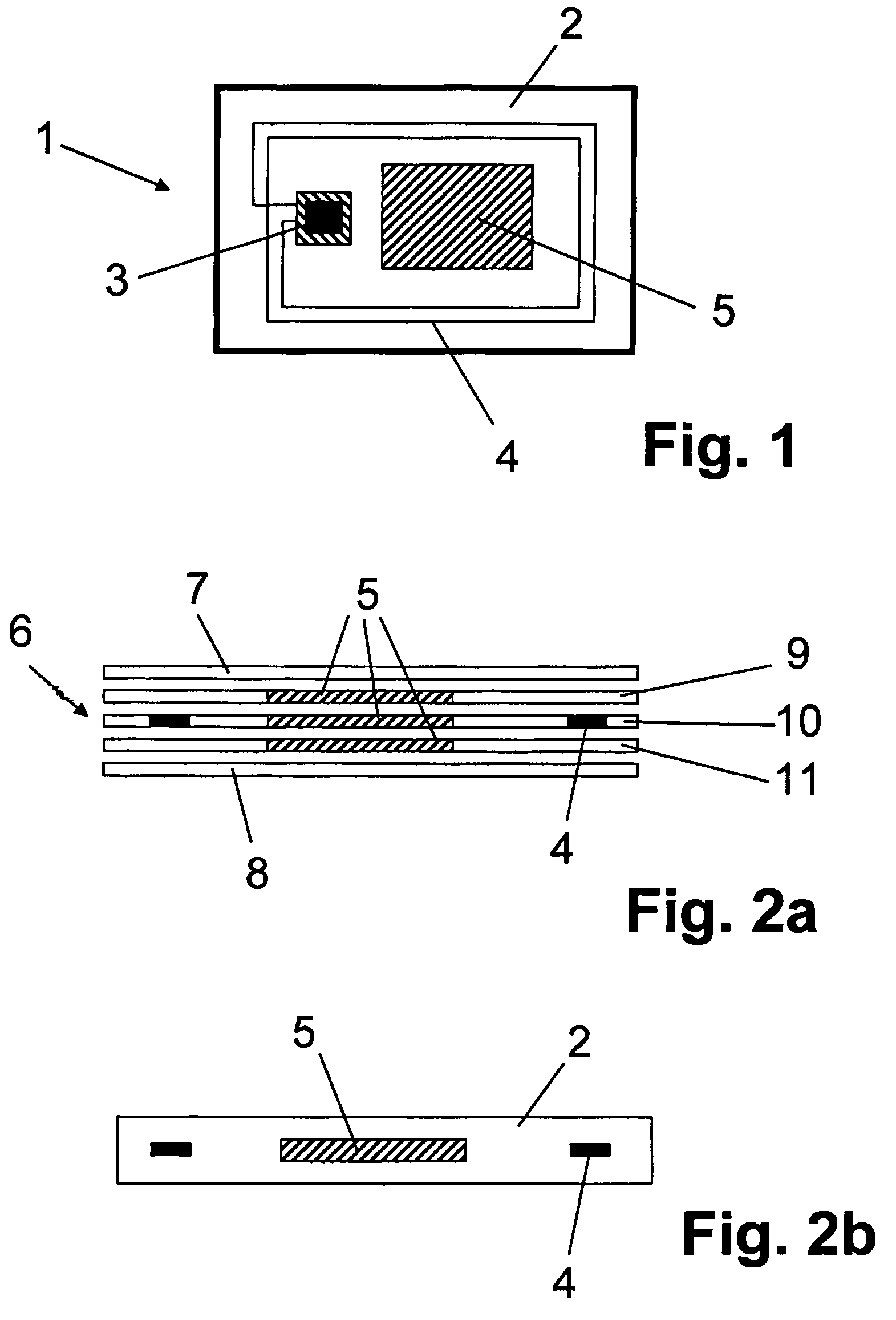
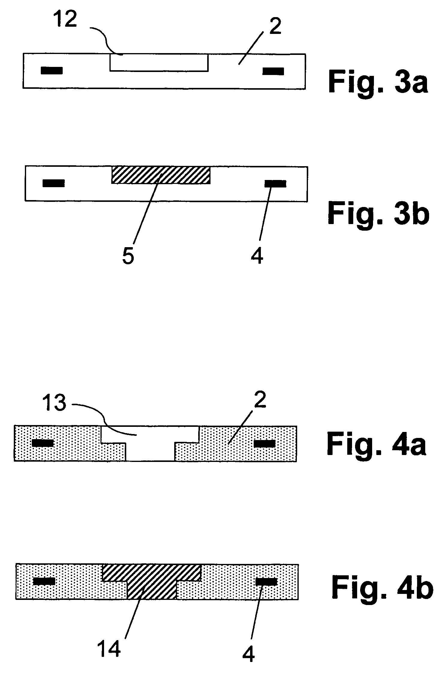
[0025]The smart card 1, illustrated in FIG. 1, comprises a card body 2. Usually, the card body 2 is formed by joining several foils of plastic material in a lamination process, where the flexible thin foils are baked together to one “hard” plastic card. Embedded in this card body 2 is a chip 3 which is electrically connected to an antenna 4 wound into the card body 2. Depending on the used chip technology it is possible to integrate the chip together with the antenna directly during the lamination process. Another possibility is to implant the chip in a recess formed in the card body after the lamination process.

[0026]The antenna 4 is used for communication with a card acceptance device (not shown) as well as for collecting energy from the electromagnetic field emitted by the card acceptance device. According to the invention said antenna 4 is provided with a metal core 5. In the here described embodiment the metal core 5 is integrated in the card body 2 together with the antenna 4 ...


PUM


Abstract

A smart card having an extended communication distance includes a card body, at least one chip and at least one antenna attached to the chip, wherein the chip and the antenna are embedded in the card body. The smart card is characterized in that the antenna is provided with at least one metal core.

Description

CROSS-REFERENCE TO RELATED APPLICATION[0001]The present application claims priority to European Patent Application Number 04106582.2, filed Dec. 14, 2004.BACKGROUND OF THE INVENTION[0002]1. Field of the Invention[0003]The present invention relates to smart cards, especially to contactless and dual interface smart cards, and to methods for producing and enhancing such smart cards to extend the communication distance where the smart card can be used reliably.[0004]2. Description of the Related Art[0005]Having the same size as a credit card, a smart card is able to store and process information by means of the electronic circuits of a chip embedded into the plastic body of the smart card. This chip also contains the processor, volatile memory, non-volatile memory and I / O support. A smart card therefore is a portable and tamper resistant computer. Unlike magnetic stripe cards, smart cards carry both processing power and information. The physical appearance and properties of a smart card...

Claims


Application Information

Patent Timeline
Patent Type & Authority Patents(United States)
IPC IPC(8): G06K19/06
CPCG06K19/07749
Inventor SCHOLZ, ANDREASSCHWARZER, STEPHAN
Owner INT BUSINESS MASCH CORP
Why Eureka
Try Eureka