Electromagnetically driven valve

a technology of electric drive and valve element, which is applied in the direction of non-mechanical valves, magnetic bodies, machines/engines, etc., can solve the problems that the driving force is not sufficient to move the valve element to the fully open position or to the fully closed position, and achieves a great driving force

Inactive Publication Date: 2007-12-11
TOYOTA JIDOSHA KK
View PDF19 Cites 3 Cited by
  • Summary
  • Abstract
  • Description
  • Claims
  • Application Information

AI Technical Summary

Benefits of technology

[0012]In the electromagnetically driven valve thus configured, the first and second coils are constituted of an identical connection. Accordingly, in an initial drive mode, when the first and second coils are supplied with a current, electromagnetic force in a direction moving the moving element toward the valve-opening position and electromagnetic force in a direction moving the moving element toward the valve-closing position are simultaneously applied to the moving element. Here, supplied with a current, the third coil generates a third magnetic flux, which reduces one of the first magnetic flux and the second magnetic flux. Thus, the electromagnetic force generated by the coil of which magnetic flux is reduced becomes smaller. Since the magnetic flux being affected by the third magnetic flux is reduced, saturation of the magnetic fluxes does not occur. Thus, a difference between the electromagnetic force in the direction moving the moving element toward the valve-opening position and the electromagnetic force in the direction moving the moving element toward the valve-closing position can be ensured, and sufficient driving force for the initial drive mode of the intake / exhaust valve can be attained. Therefore, according to the present invention, the intake / exhaust valve can be shifted in a short period from the intermediate position to the valve-opening position or the valve-closing position.
[0014]Preferably, the third coil is supplied with a current only in the initial drive mode of the internal combustion engine. With the electromagnetically driven valve thus configured, by supplying the third coil with a current only in the initial drive mode where great driving force is required, unnecessary power consumption in the normal driving mode after the internal combustion engine is started can be prevented.
[0015]The moving element has a support portion rotatably supported, and oscillates between the valve-opening position and the valve-closing position about the support portion as a fulcrum. The moving element is provided in a plurality of numbers with a distance from each other. The electromagnet is arranged between the plurality of moving elements. With the electromagnetically driven valve of rotary drive type employing such a parallel link mechanism also, one of the aforementioned effects can similarly be attained.

Problems solved by technology

However, since the difference between the electromagnetic forces respectively applied to the two moving elements is small, the driving force sufficient for moving the valve element to the fully open position or to the fully closed position cannot be attained.

Method used


Image

  • Electromagnetically driven valve
  • Electromagnetically driven valve
  • Electromagnetically driven valve

Examples


first embodiment

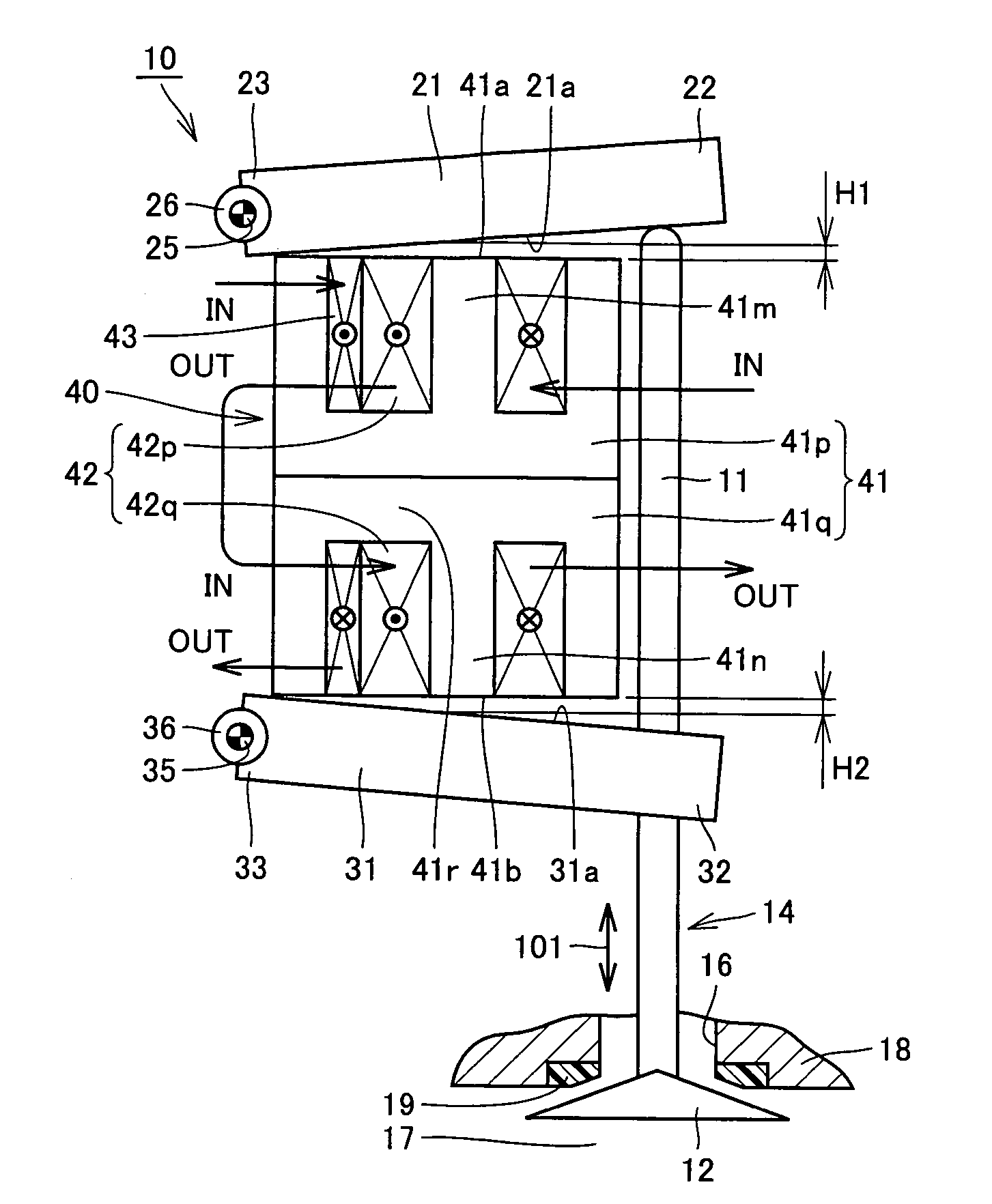
[0024]FIG. 1 shows an electromagnetically driven valve according to a first embodiment of the present invention. The electromagnetically driven valve according to the present embodiment implements an engine valve (an intake valve or an exhaust valve) in an internal combustion engine such as a gasoline engine or a diesel engine. In the present embodiment, description will be given assuming that the electromagnetically driven valve implements an exhaust valve, however, the electromagnetically driven valve is similarly structured also when it implements an intake valve.

[0025]Referring to FIG. 1, an electromagnetically driven valve 10 is a rotary drive type electromagnetically driven valve, driven by cooperation of magnetic force and elastic force. As a motion mechanism for the electromagnetically driven valve, a parallel link mechanism is adopted.

[0026]Electromagnetically driven valve 10 includes a driven valve 14, a valve-opening side moving element 21 and a valve-closing side moving ...

second embodiment

[0049]FIG. 5 shows an electromagnetically driven valve in a second embodiment of the present invention. The electromagnetically driven valve in the present embodiment includes, in comparison with electromagnetically driven valve 10 in the first embodiment, partially the same structure. In the following, description of the overlapping structure will not be given.

[0050]Referring to FIG. 5, in the present embodiment, valve-opening side moving element 21 and valve-closing side moving element 31 shown in FIG. 1 are not provided, and a moving element 61 is provided instead. Moving element 61 is formed from a magnetic material, and has a support portion 63, a coupling portion 62 and a surface 61a, corresponding to support portion 23, coupling portion 22 and surface 21a of valve-opening side moving element 21 shown in FIG. 1. Moving element 61 further has a surface 61b opposite to surface 61a. At support portion 63, a central axis 65 to be the center of the oscillating movement of moving el...


PUM


Abstract

The electromagnet includes a valve-opening side coil portion supplied with a current to thereby generate a first magnetic flux and generate electromagnetic force in a direction moving the valve-opening side moving element toward a valve-opening position, and a valve-closing side coil portion supplied with a current to thereby generate a second magnetic flux and generate electromagnetic force in a direction moving the valve-closing side moving element toward the valve-closing position. The valve-opening side coil portion and the valve-closing side coil portion are constituted of an identical connection. The electromagnet further has a sub-coil constituted of a separate connection from the valve-opening side coil portion and the valve-closing side coil portion. By the current supply to the sub-coil, a third magnetic flux reducing at least one of the first magnetic flux and the second magnetic flux is generated.

Description

[0001]This nonprovisional application is based on Japanese Patent Application No. 2005-161610 filed with the Japan Patent Office on Jun. 1, 2005, the entire contents of which are hereby incorporated by reference.BACKGROUND OF THE INVENTION[0002]1. Field of the Invention[0003]The present invention generally relates to an electromagnetically driven valve, and more particularly to an electromagnetically driven valve wherein a coil for lifting an intake / exhaust valve in a valve-opening direction and a coil for lifting the same in a valve-closing direction are constituted of an identical connection.[0004]2. Description of the Background Art[0005]As to a conventional electromagnetically driven valve, for example Japanese Patent Laying-Open No. 2002-115515 discloses an actuator for an electromagnetically driven valve having an object of facilitating mounting on a vehicle and to reduce weight and costs (Patent Document 1). The actuator for an electromagnetically driven valve disclosed in Pa...

Claims


Application Information

Patent Timeline
Patent Type & Authority Patents(United States)
IPC IPC(8): F16K31/02F01L9/20
CPCF01L9/04F01L2009/0409F01L2009/0405F01L2009/2105F01L2009/2109F01L9/20
Inventor NAKAMURA, KIYOHARUSUGIE, YUTAKA
Owner TOYOTA JIDOSHA KK
Why Eureka
Try Eureka