Drill with groove width variation along the drill and double margin with a thinning section at the tip

a technology of groove width variation and drill bit, which is applied in the field of drill bit, can solve the problems of increased susceptibility to breakage, insufficient rigidity, and decrease in thickness of drill bit, and achieve the effect of improving the wear resistance of the drilling end section, reducing surface roughness, and improving the wear resistance of the drilling bi

Inactive Publication Date: 2007-12-11
MITSUBISHI MATERIALS CORP
View PDF43 Cites 42 Cited by
  • Summary
  • Abstract
  • Description
  • Claims
  • Application Information

AI Technical Summary

Benefits of technology

[0022]According to this drill, together with the chip discharge groove being widened towards the direction of drill rotation relative to the narrow width section on the tip side in the wide width section, since it is also widened towards the rear in the direction of drill rotation, chips located towards the rear in the direction of drill rotation of this chip discharge groove that slide through while pressing against the wall surface facing in the direction of drill rotation can be reliably fed to the rear end side and discharged.
[0043]This polishing is carried out by polishing the inner peripheral surface of the chip discharge groove with a brush coated with an abrasive such as diamond paste. The surface roughness of the inner peripheral surface of the chip discharge groove polished in this manner is preferably within the range of 0.5-1.5 μm in the direction in which the chip discharge groove extends, and within the range of 1.0-2.0 μm in the circumferential direction of the inner peripheral surface. The greater the surface roughness exceeds the above ranges, the less the effect of reducing friction generated by sliding contact of the chips, and conversely, the greater the surface roughness falls below the above ranges, the greater the amounts of time and labor required for polishing. In addition, it is preferable that the surface roughness on the inner peripheral surface of the polished chip discharge groove as measured in the direction in which the chip discharge groove extends be smoother than the surface roughness as measured in the circumferential direction of the inner peripheral surface.

Problems solved by technology

If the location of this boundary is farther towards the tip than this range, the proportion of section where the groove width is large of the chip discharge groove extending from the expanding width section farther towards the rear end side to the wide width section becomes excessively large, resulting in a decrease in thickness of the drill body and insufficient rigidity, thereby resulting in the possibility of increased susceptibility to breakage during drilling.
Conversely, if the location of the boundary is farther towards the rear end side than the above range, the length of the narrow width section of the chip discharge groove farther towards the tip becomes long, resulting in the possibility of chips becoming clogged in this narrow width section.

Method used


Image

  • Drill with groove width variation along the drill and double margin with a thinning section at the tip
  • Drill with groove width variation along the drill and double margin with a thinning section at the tip
  • Drill with groove width variation along the drill and double margin with a thinning section at the tip

Examples


example

[0150]A drilling test was conducted using a double margin type drill based on the embodiment shown in FIGS. 11 through 17 as an example of the present invention and a double margin type drill of the prior art as an example of the prior art for the purpose of explaining the effects of the drill shown in FIGS. 11 through 17. Those results are shown in FIG. 18.

[0151]In the example of the present invention, in contrast to the inner wall surface roughness of the entrance section and exit section of a machined hole being satisfactorily maintained at a low level, in the example of the prior art, the inner wall surface roughness of the entrance and exit sections of a machined hole were found to become worse.

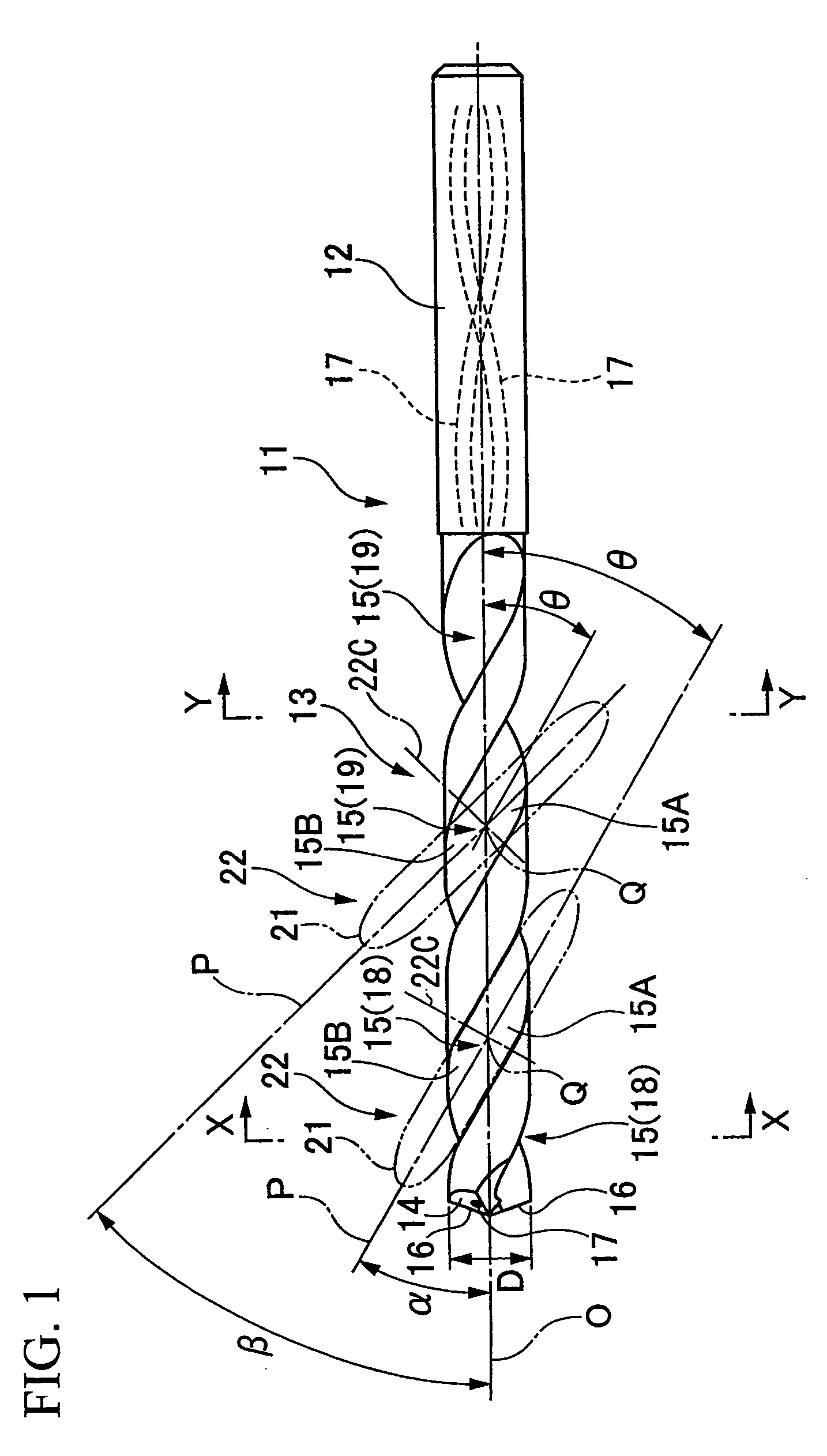
[0152]FIGS. 19 through 21 show still another embodiment of the drill of the present invention.

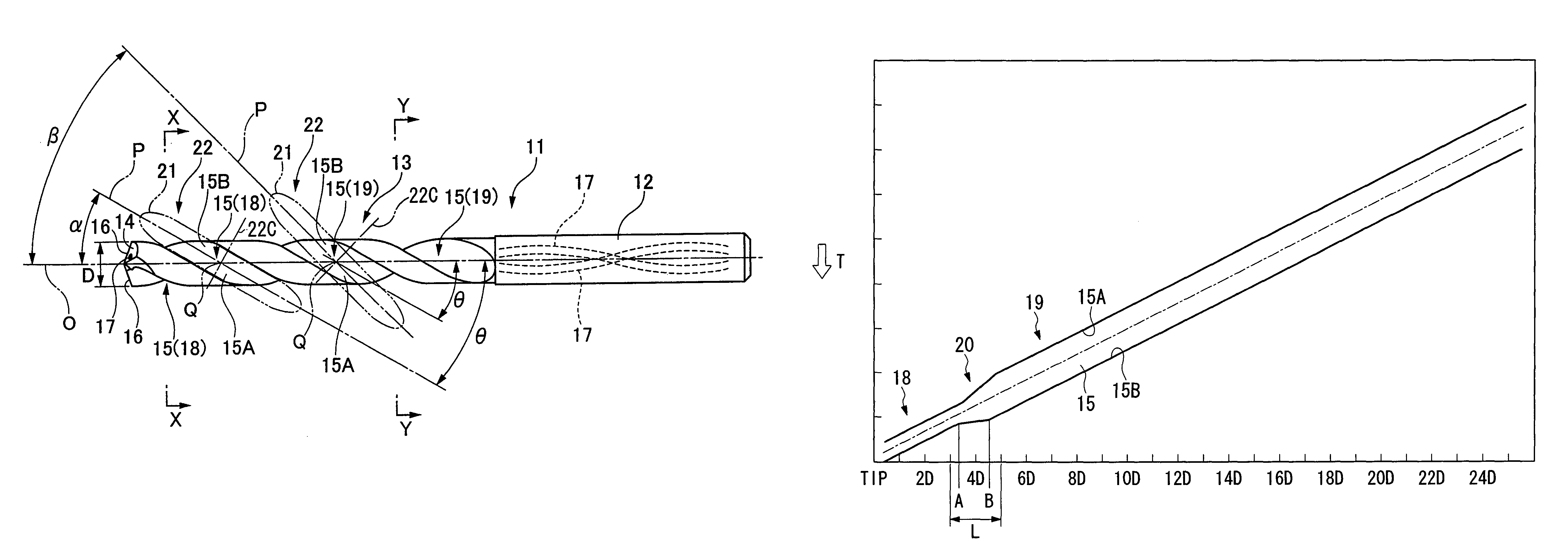
[0153]In the drill of the present embodiment, drill body 201 is composed of a member formed by a hard material such as cemented carbide and is roughly in the shape of a cylindrical column center...


PUM

PropertyMeasurementUnit
surface roughnessaaaaaaaaaa
angleaaaaaaaaaa

Abstract

In a drill in which a chip discharge groove twisted in the shape of a spiral relative to an axis is formed in the outer periphery of the tip section of a roughly cylindrical drill body that rotates around the axis, and a cutting edge is formed on the intersecting ridgeline between a wall surface facing in the direction of drill rotation of this chip discharge groove and a tip flank of the drill body, together with the section on the tip side of the chip discharge groove continuous with the cutting edge being a narrowed width section in which the helix angle relative to the axis and groove width are constant, a wide width section is formed in the chip discharge groove farther towards the rear end than this narrow width section, in which the helix angle is equal to the narrow width section and in which the groove width is widened relative to the narrow width section in the direction of drill rotation and towards the rear in the direction of drill rotation and has a constant width.

Description

BACKGROUND OF THE INVENTION[0001]1. Field of the Invention[0002]The present invention relates to a drill, in which a spiral-shaped chip discharge groove is formed in the outer periphery of the tip section of the drill body, and a production method thereof. In addition, the present invention relates to a drill used for hole drilling in order to form a machined hole at a high level of hole positioning accuracy in a drilled material, and for example, relates to a drill for forming a deep machined hole in a metal material.[0003]2. Background Art[0004]As shown in FIG. 22 through FIG. 24, a known example of a drill (solid drill) in which a spiral-shaped chip discharge groove is formed in the outer periphery of the end section of the drill body is a so-called two-flute twist drill in which a pair of chip discharge grooves 2, which twist to the rear in the direction of rotation of the drill around an axis O towards the rear end from the tip flank of the drill body, are formed symmetrically ...

Claims


Application Information

Patent Timeline
Patent Type & Authority Patents(United States)
IPC IPC(8): B23B51/02B23B51/06B23B51/00B24B19/04
CPCB23B51/02B24B3/24B24B19/04B23B51/06Y10T408/78B23B2224/24B23B2224/28B23B2224/32B23B2224/36B23B2228/10B23B2251/04B23B2251/046B23B2251/14B23B2251/18B23B2251/406B23B2251/422B23B2251/443Y10T408/909Y10T408/9097B23B51/063
Inventor MABUCHI, MASAYUKIYANAGIDA, KAZUYASUZUKI, KATSUYUKITAKIGUCHI, SYOJI
Owner MITSUBISHI MATERIALS CORP
Why Eureka
Try Eureka