Sealing arrangement for the attachment of a side plate of a centrifugal pump and an attachment screw used therewith

a technology of centrifugal pump and side plate, which is applied in the direction of leakage prevention, motors, liquid fuel engines, etc., can solve the problems of liquid to be pumped, reduced pump efficiency, and increased clearance of volute front wall, so as to improve the cost efficiency, increase the competitiveness, and increase the cost

Active Publication Date: 2007-12-11
SULZER MANAGEMENT AG
View PDF4 Cites 10 Cited by
  • Summary
  • Abstract
  • Description
  • Claims
  • Application Information

AI Technical Summary

Benefits of technology

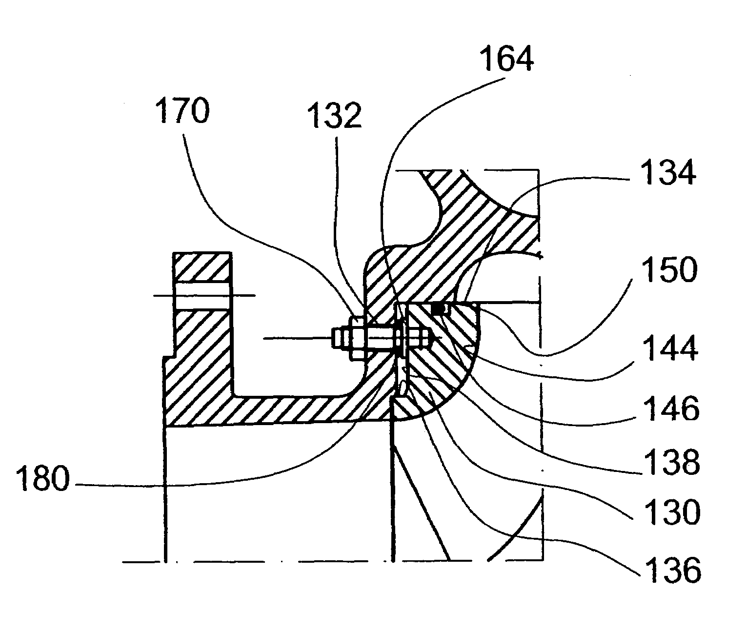
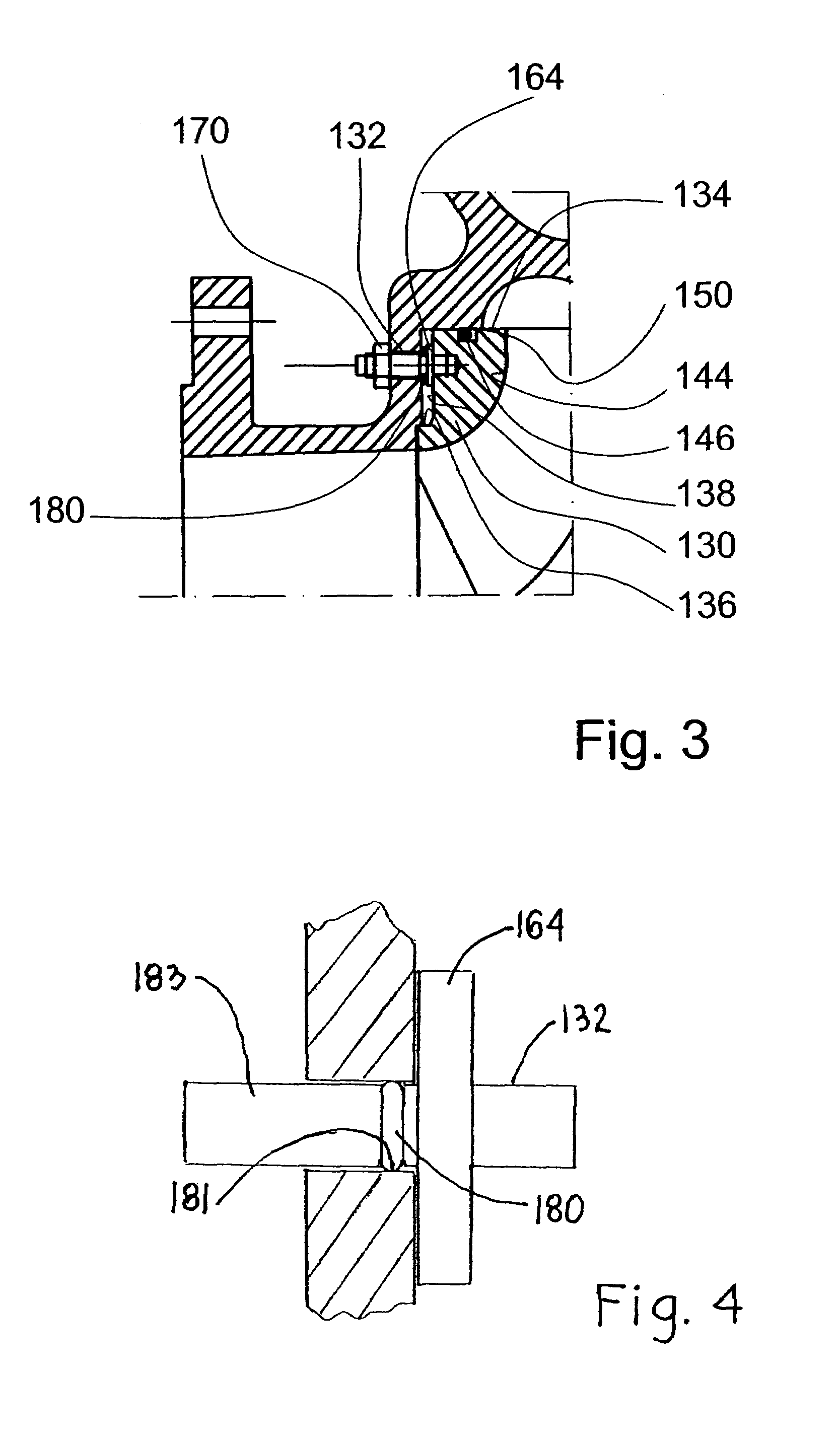
[0007]In other words, a large O-ring is located, according to a preferred embodiment of the invention, at the outer rim of the side plate to seal and to separate a leakage flow from the pressure side to the suction side of the pump, and a small O-ring is located between a flange of the attachment screw and the pump volute to seal the gap therebetween and prevent the leakage fluid from flowing out. The large O-ring does not have to be completely leak-proof, but the smaller O-ring must endure both the mechanical and chemical loads, and, if necessary, materials, such as FFKM or like, enduring aggressive chemicals must be used as the seal ring material. Thanks to the small O-ring, which is inexpensive to acquire, the structure of the invention becomes significantly more cost-effective and therefore also more competitive.

Problems solved by technology

However, when pumping even slightly erosive fluids, such as different suspensions, especially the edges of the impeller vanes facing the volute are subjected to wearing, whereby the clearance thereof to the front wall of the volute increases and the efficiency of the pump is reduced.
If the O-rings leak for some reason, the liquid to be pumped leaks to the back side of the side plate and the adjustment screws get into contact with the liquid.
This is not as such detrimental, but a problem arises because the liquid to be pumped is able to leak through the openings arranged for the adjustment or attachment screws in the volute to the outside of the pump.
There are, of course, O-rings manufactured of modern materials, which rings could be used in the above-described positions, but as they are large rings, they are almost as expensive as the rest of the pump.
Because of the high price, such a construction is not competitive on the market.

Method used


Image

  • Sealing arrangement for the attachment of a side plate of a centrifugal pump and an attachment screw used therewith
  • Sealing arrangement for the attachment of a side plate of a centrifugal pump and an attachment screw used therewith
  • Sealing arrangement for the attachment of a side plate of a centrifugal pump and an attachment screw used therewith

Examples


Embodiment Construction

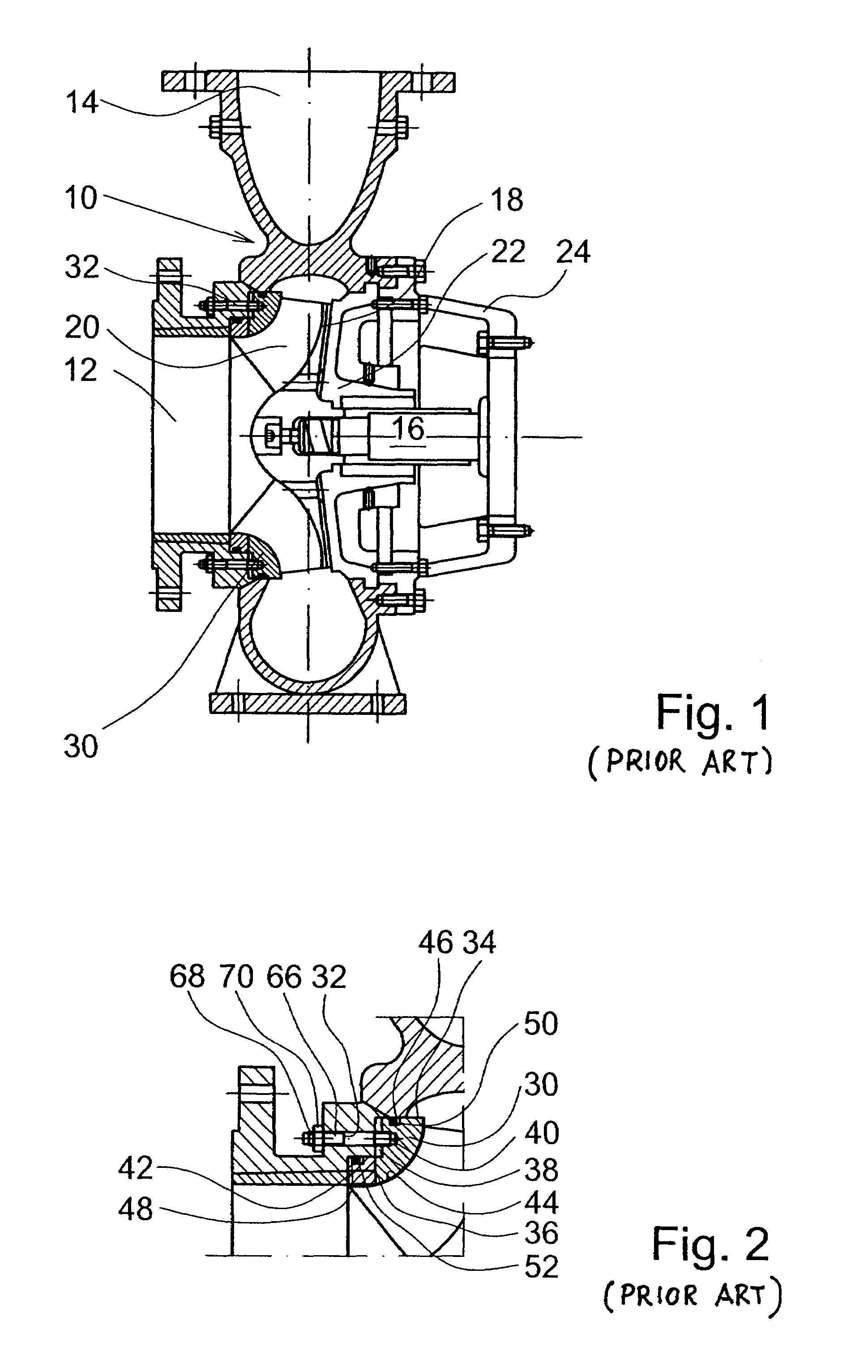
[0014]According to FIG. 1, a centrifugal pump in accordance with the prior art comprises a volute 10 with a suction opening 12 and a pressure opening 14, an impeller 18 with working vanes 20 located on a shaft 16 inside the volute 10, a pump rear wall 22 and a pump casing 24 with bearings. The drawing also illustrates a so-called adjustable side plate 30 of the volute 10, attached to the volute preferably with at least three adjustment screws 32.

[0015]FIG. 2 illustrates the structure and attachment of the side plate 30 in accordance with prior art more in detail. The side plate 30 is an annular member with two radially outwards opening cylindrical surfaces 34 and 36. The surface 34 is located at the outer rim of the side plate 30 and guides the side plate 30 inside a larger cylindrical surface of the volute 10 within a small clearance therefrom. A second cylindrical surface 36 of the side plate 30 with a smaller diameter is located against a corresponding cylindrical surface of the ...


PUM


Abstract

The present invention relates to a sealing arrangement for attaching a side plate often used with a pump volute of a centrifugal pump and an attachment screw used therewith. A characterizing feature of the sealing arrangement for attaching the side plate of a centrifugal pump, comprising at least a pump volute (10) and a side plate (130) with attachment screws (132) and flanges (164) of the screws (132) arranged in communication with the volute (10) or the cover of the casing, is that an annular seal (180) is arranged between the screw (132) and the volute or the cover of the casing.

Description

BACKGROUND OF THE INVENTION[0001]The present invention relates to a sealing arrangement for the attachment of a side plate often used in connection with a pump volute of a centrifugal pump and an attachment screw used therewith.[0002]A centrifugal pump comprises, as known, mainly a so-called volute with a suction opening, a discharge opening, and an impeller rotating inside the volute. Since the efficiency and capacity of the pump are substantial both for the manufacturer, seller and especially for the end user, the clearances between the impeller and the volute must be optimal, in other words in most cases as small as possible. By using modern production methods, it is possible to manufacture optimal clearances in new pumps. However, when pumping even slightly erosive fluids, such as different suspensions, especially the edges of the impeller vanes facing the volute are subjected to wearing, whereby the clearance thereof to the front wall of the volute increases and the efficiency ...

Claims


Application Information

Patent Timeline
Patent Type & Authority Patents(United States)
IPC IPC(8): F04D29/44F04D29/16
CPCF04D29/167F04D29/622
Inventor AHLROTH, JUSSILEHTONEN, JORMA
Owner SULZER MANAGEMENT AG
Why Eureka
Try Eureka