Terminal crimping structure and terminal crimping method onto aluminum electric-wire and producing method of aluminum electric-wire with terminal

a technology of terminal crimping and aluminum electric wire, which is applied in the direction of line/current collector details, electrical equipment, and connections effected by permanent deformation, etc., and can solve problems such as defective conduction, conduction defect, and melting

Active Publication Date: 2007-12-11
FURUKAWA ELECTRIC CO LTD
View PDF10 Cites 69 Cited by
  • Summary
  • Abstract
  • Description
  • Claims
  • Application Information

AI Technical Summary

Benefits of technology

[0023]It is therefore an object of the present invention to provide a terminal crimping structure and a terminal crimping method onto aluminum electric-wire as well as a producing method of an aluminum electric-wire with a terminal, for allowing electric characteristics of connected portions to be maintained irrespectively of an environmental change, upon crimping the terminal onto the aluminum electric-wire.
[0024]It is a further object of the present invention to provide a terminal structure having a necessary terminal crimping strength (electric-wire retaining force of the terminal) while ensuring a sufficient electric conducting property between the aluminum electric-wire and the terminal, upon crimping the terminal onto the aluminum electric-wire.

Problems solved by technology

Thus, electric current is flowed through limited strands to thereby easily cause a constriction resistance which in turn leads to a risk of: occurrence of melting; and defective conduction.
When aluminum electric-wires are actually crimped with terminals under the same conditions as copper electric-wires, resistances at terminal-crimped portions are increased due to environmental variations such as raised or lowered temperatures to thereby cause defects of conduction, thereby failing to maintain electric connecting states at satisfactory levels between terminals and electric-wires.
However, aluminum electric-wires have weaker mechanical strengths and lower melting temperatures as compared with copper electric-wires, and have such properties that each of the strands constituting the aluminum electric-wire is apt to form an oxide film.
Thus, electric current is flowed through limited strands to thereby easily cause a constriction resistance which in turn leads to a risk of: occurrence of melting; and defective conduction.
However, the electric-wire retaining force is extremely deteriorated due to the excessive stress affecting the terminal-crimped portion, thereby possibly resulting in an inappropriate connecting structure when used between a terminal and an electric-wire.
In the crimped state shown in FIG. 3B which is the same as the conventional copper electric-wire, although the terminal crimping strength (electric-wire retaining force) is not problematic, oxide films on the surfaces of the strands of the electrical conductor part 501a are not sufficiently broken, and there is caused an increased contact resistance in an environmental test such as thermal cycles, thereby resulting in an insufficient electric conducting property.
Meanwhile, when the terminal 580 is crimped onto the aluminum electric-wire 501 at a higher compressed ratio (surface-area reducing ratio) as shown in FIG. 3C, electric conduction is certainly and sufficiently achieved, but the electric-wire retaining force is deteriorated due to the increased stress affecting the terminal-crimped portion of the electric-wire, thereby failing to obtain a terminal crimping strength required for each electric-wire size.

Method used


Image

  • Terminal crimping structure and terminal crimping method onto aluminum electric-wire and producing method of aluminum electric-wire with terminal
  • Terminal crimping structure and terminal crimping method onto aluminum electric-wire and producing method of aluminum electric-wire with terminal
  • Terminal crimping structure and terminal crimping method onto aluminum electric-wire and producing method of aluminum electric-wire with terminal

Examples


example 1

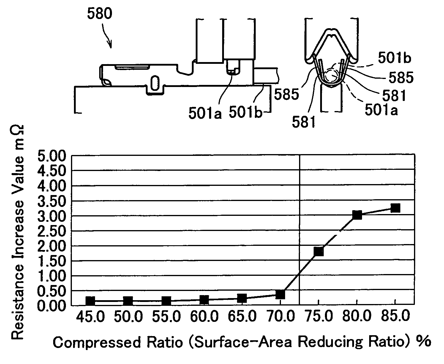
[0097]Terminals were crimped onto aluminum electric-wires having electrical conductor parts of various cross-sectional areas at various compressed ratios, and there was conducted such a thermal shock test, i.e., a test for continuously and alternately repeating a low temperature environment (−40° C.) and a high temperature environment (120° C.), for these aluminum electric-wires with crimped terminals. Further, the external appearances of the terminal-crimped portions before and after the test were compared with each other, and there were measured the resistance change and the like of the electrically connected portions before and after the test.

[0098]This thermal shock test is suitable for evaluating a connecting ability of a terminal-crimped portion. Further, the thermal shock test was performed by 1,000 cycles.

[0099]Listed in Table 1 are representative resistance increase values between before and after the environmental test (thermal shock test). Further, FIG. 8 shows a graph pl...

example 2

[0119]This Example 2 is to prove why the lower limit value of the compressed ratio is defined to be 40% in crimping a terminal onto an aluminum electric-wire including an electrical conductor part having a cross-sectional area of 1.5 mm2 or more.

[0120]Concretely, the smaller the concrete numerical value of the compressed ratio, the smaller the above described resistance increase value in the similar manner. Meanwhile, in case of an aluminum electric-wire including an electrical conductor part having a cross-sectional area less than 1.5 mm2, the lower limit value of compressed ratio is preferably considered to be 50%, because the crimping strength is considerably deteriorated and the mechanical connecting strength at the terminal-crimped portion is deteriorated when the compressed ratio is less than 50%, i.e., when the electrical conductor's cross-sectional area before crimping the terminal is highly compressed to ½ or less after crimping the terminal. Nonetheless, it has been found ...

example 3

[0138]In the Example 3, the present inventor has adopted an aluminum electric-wire, which is a slightly larger size of 2.5 mm2 and which includes typically used constitution, material, refinement and the like under the condition that the cross-sectional area of the aluminum electric-wire's conductor part is 1.5 mm2 or more, thereby investigating a relationship between the compressed ratio and the crimping strength in this aluminum electric-wire and the terminal. The result thereof is shown in the following Table 3 and FIG. 12.

[0139]

TABLE 3Compressed ratio (%)25.030.035.040.045.050.055.060.065.070.0Terminal120.0146.3169.6186.4195.8204.1218.9235.8247.0274.1crimpingstrength (N)

[0140]As understood from this test result, although the crimping strength is considerably deteriorated when the electrical conductor's cross-sectional area is highly compressed to ½, the crimping strength of 100N can be satisfied even when the compressed ratio becomes less than 50% (½) since larger sizes (mm2) le...


PUM


Abstract

A terminal crimping structure onto aluminum electric-wire, for crimping a terminal onto an aluminum electric-wire including: an electrical conductor part comprising numerous strands; and a coating part coated on the . electrical conductor part; wherein the terminal has a wire barrel to be crimped onto the electrical conductor part of the aluminum electric-wire; and wherein the compressed ratio of the aluminum electric-wire's conductor part by the wire barrel is within a range of 50 to 70%, in terms of the ratio of (cross-sectional area of aluminum electric-wire's conductor part at crimped portion) / (cross-sectional area of aluminum electric-wire's conductor part before crimping).

Description

BACKGROUND[0001]1. Field of the Invention[0002]The present invention relates to a terminal crimping structure and a terminal crimping method onto aluminum electric-wire, the terminal being used to be crimped onto the aluminum electric-wire and mounted within a connector housing, and relates to a producing method of an aluminum electric-wire with a terminal.[0003]2. Description of the Related Art[0004]There will be firstly described an object of the present invention. Conventionally, wire harnesses such as arranged within vehicular compartments have been typically made of copper electric-wires, and it has been rare to use aluminum electric-wires having deteriorated properties (physical properties) such as electric conductivity and strength. However, there have been recently increased such demands for using aluminum electric-wires, so as to reduce weights of vehicles and in view of recycling ability of the aluminum electric-wires. Meanwhile, electrical connectors have been typically u...

Claims


Application Information

Patent Timeline
Patent Type & Authority Patents(United States)
IPC IPC(8): H01R4/10H01R4/18H01R43/048
CPCH01R4/185H01R43/0488
Inventor HASHIMOTO, TOSHIYUKIKANEKO, SHUHEI
Owner FURUKAWA ELECTRIC CO LTD
Why Eureka
Try Eureka