Access annunciator

an access annunciator and access technology, applied in the field of alarms, can solve problems such as manipulation, manipulation, and manipulation, and achieve the effect of less expensive and simple operation

Inactive Publication Date: 2007-12-11
ADAMS ALBERT GEORGE
View PDF13 Cites 9 Cited by
  • Summary
  • Abstract
  • Description
  • Claims
  • Application Information

AI Technical Summary

Benefits of technology

[0006]It is a principal advantage of the present invention to provide an alert system which is simpler in operation that currently known devices. It is again to be emphasized that the present invention does not serve to replace, or improve on the conventional alarm systems; and that it merely fills the need for a more simple, and less expensive means of illegal entry recordal or notification.
[0007]As such, the advantages set out hereinabove, as well as other objects and goals inherent thereto, are at least partially or fully provided by the access annunciator of the present invention, as set out herein below.
[0008]Accordingly, in one aspect, the present invention provides a device for informing on entry gained within any enclosure having an access opening, which device comprises a pulsed switching means, and an alert signaling means for generating an alert signal when activated by said pulsed switching means.
[0009]The pulsed switching means is merely any switch or device which can provided an on / off signal when engaged or contacted.
[0010]Accordingly, the present invention comprises principal components that, when installed, will function as a sealed tamper proof annunciating device, small enough for inconspicuous insertions, or surface mounting.
[0011]Further, the device provides the features of a substantial switching means, which will essentially energizing an alert device on its' sequential third attempt. Thereby said alert device remains in an energized state on all subsequent attempts, and does not change status until manually reset. This represents one complete functional cycle of said invention.

Problems solved by technology

This gives rise to the temptation of tampering and manipulative exploitation of the keypad coding system within its' control center.

Method used


Image

  • Access annunciator
  • Access annunciator
  • Access annunciator

Examples


Embodiment Construction

[0035]The novel features which are believed to be characteristic of the present invention, as to its structure, organization, use and method of operation, together with further objectives and advantages thereof, will be better understood from the following drawings in which a presently preferred embodiment of the invention will now be illustrated by way of example only. In the drawings, like reference numerals depict like elements.

[0036]It is expressly understood, however, that the drawings are for the purpose of illustration and description only and are not intended as a definition of the limits of the invention.

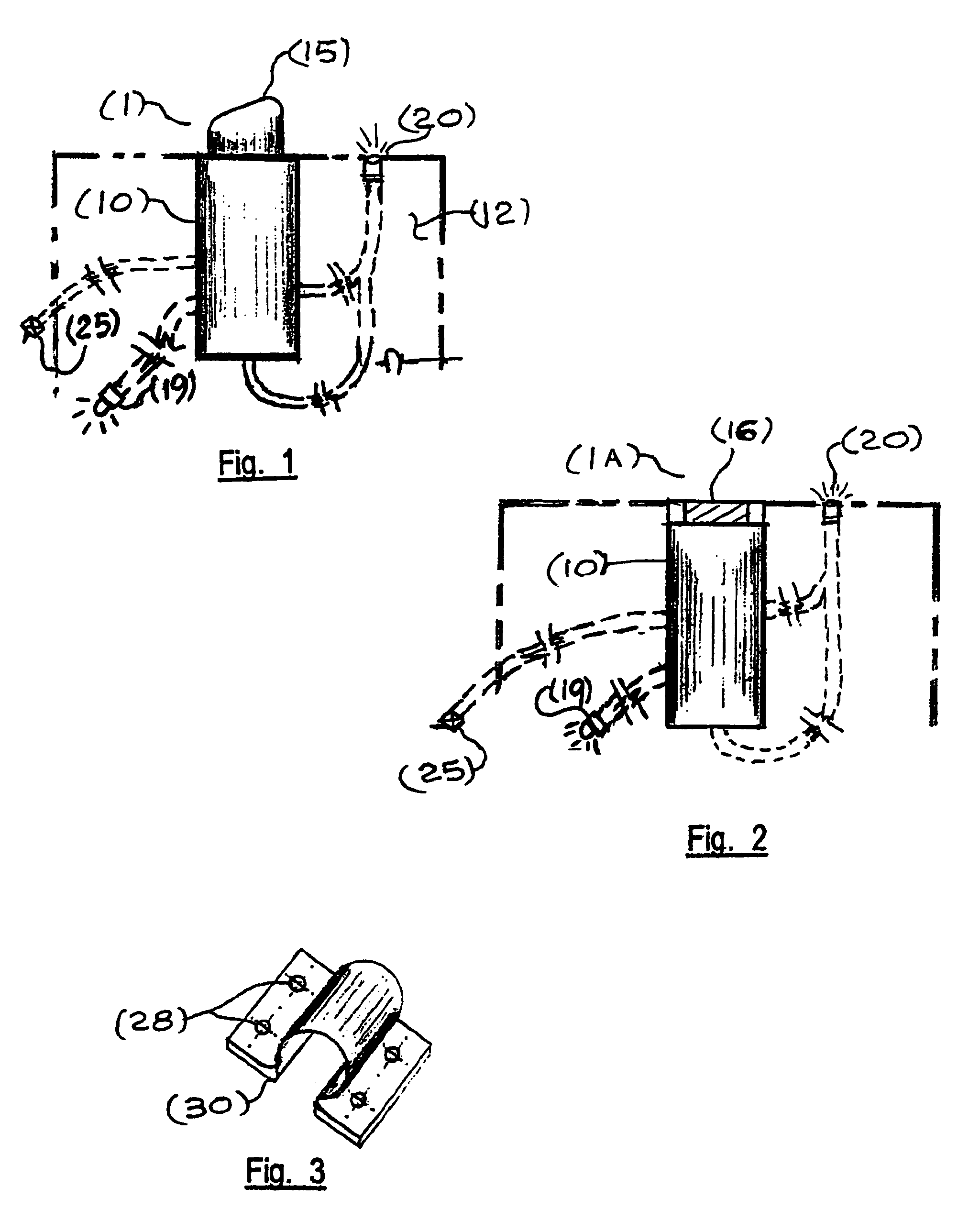
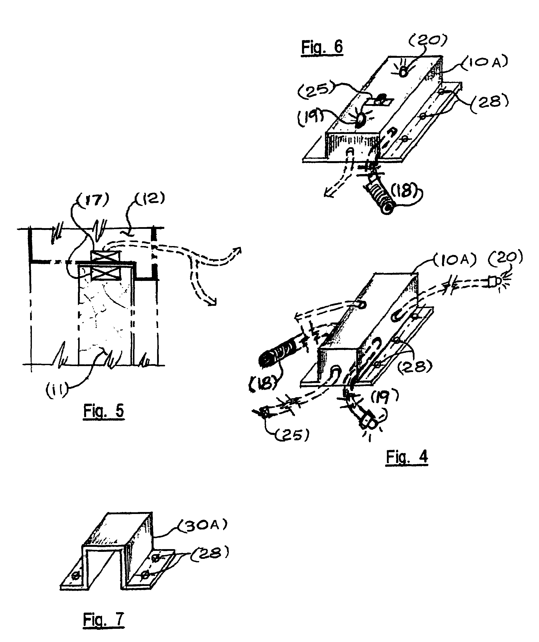
[0037]In FIG. 1, one type of an “insertion” Annunciator (1) is shown, comprising a momentary switching means (15), as well as various components and necessary semiconductors as may be found necessary, all of which are housed within or connected to, the same principal unit (10), and which are adapted to be installed within, for example, a door, or its' adjacent access openin...


PUM


Abstract

An electronic device is provided that functions as an area-intrusion informing embodiment for announcing the unauthorized entry into an enclosure or area which has at least one access opening and closing means. The invention is not intended to replace conventional alarm systems, but to provide its' own unique functional identity. The Invention comprises components that, when installed, will function as a tamper proof device, whose components are packaged in a combination of at least one container, to facilitate remoteness, and substantially small for inconspicuous insertions, or surface mounting. The Access Annunciator is ideal for access doors, windows, filing cabinets, desk draws, closets, and the like, and typically includes at least one light emitting diode, an optional numeric liquid crystal display, a timer, an alert signaling means, and resetting means. The components act together to provide notification of illegal entry between the times of departure, and arrival, of authorized users of the enclosure or area. A simpler security alert system is provided.

Description

CROSS REFERENCE TO RELATED APPLICATIONS[0001]This application is a continuation-in-part application of U.S. patent application Ser. No. 10 / 902,098, filed Jul. 30, 2004 now U.S. Pat. No. 7,081,826, which application claimed the benefit of priority under 35 U.S.C. § 119(e) to U.S. Provisional Application Ser. No. 60 / 490,957, filed on Jul. 30, 2003. The entirety of both documents are incorporated herein by reference.FIELD OF THE INVENTION[0002]This invention relates to an alarm, or more simply, to an “alert” system, for notifying a user of unauthorized entry into a place or location. In particular, a simpler form of an alarm system is provided.BACKGROUND OF THE INVENTION[0003]Conventional alarm systems are well known in the art. Commonly, known burglar alarm systems commence their functional cycle as the occupant prepares to leave the protected area. The system displays the security status of each zoning area and if verified satisfactory, the system will then allow itself to be armed b...

Claims


Application Information

Patent Timeline
Patent Type & Authority Patents(United States)
IPC IPC(8): G08B13/08G08B21/18
CPCG08B5/00G08B13/08G08B13/149G08B13/19632G08B21/24G08B13/19673G08B13/19684G08B13/19697G08B21/18G08B13/19634A45C13/24
Inventor ADAMS, ALBERT GEORGE
Owner ADAMS ALBERT GEORGE
Why Eureka
Try Eureka