Heat sink assembly having retaining device with relatively better heat dissipation effectiveness

a technology of heat dissipation device and heat sink, which is applied in the direction of indirect heat exchanger, lighting and heating apparatus, and semiconductor/solid-state device details, etc., can solve the problems of many electronic devices such as chipsets and rams that would generate large amounts of heat, malfunction or damage, and achieve better heat dissipation effect

Active Publication Date: 2007-12-11
MALICO
View PDF5 Cites 17 Cited by
  • Summary
  • Abstract
  • Description
  • Claims
  • Application Information

AI Technical Summary

Benefits of technology

[0006]It is therefore an object of the present invention to propose a heat sink a...

Problems solved by technology

Nowadays, many electronic devices such as chipsets and RAMs would generate large amounts of heat during the operation.
Oth...

Method used


Image

  • Heat sink assembly having retaining device with relatively better heat dissipation effectiveness
  • Heat sink assembly having retaining device with relatively better heat dissipation effectiveness
  • Heat sink assembly having retaining device with relatively better heat dissipation effectiveness

Examples


Embodiment Construction

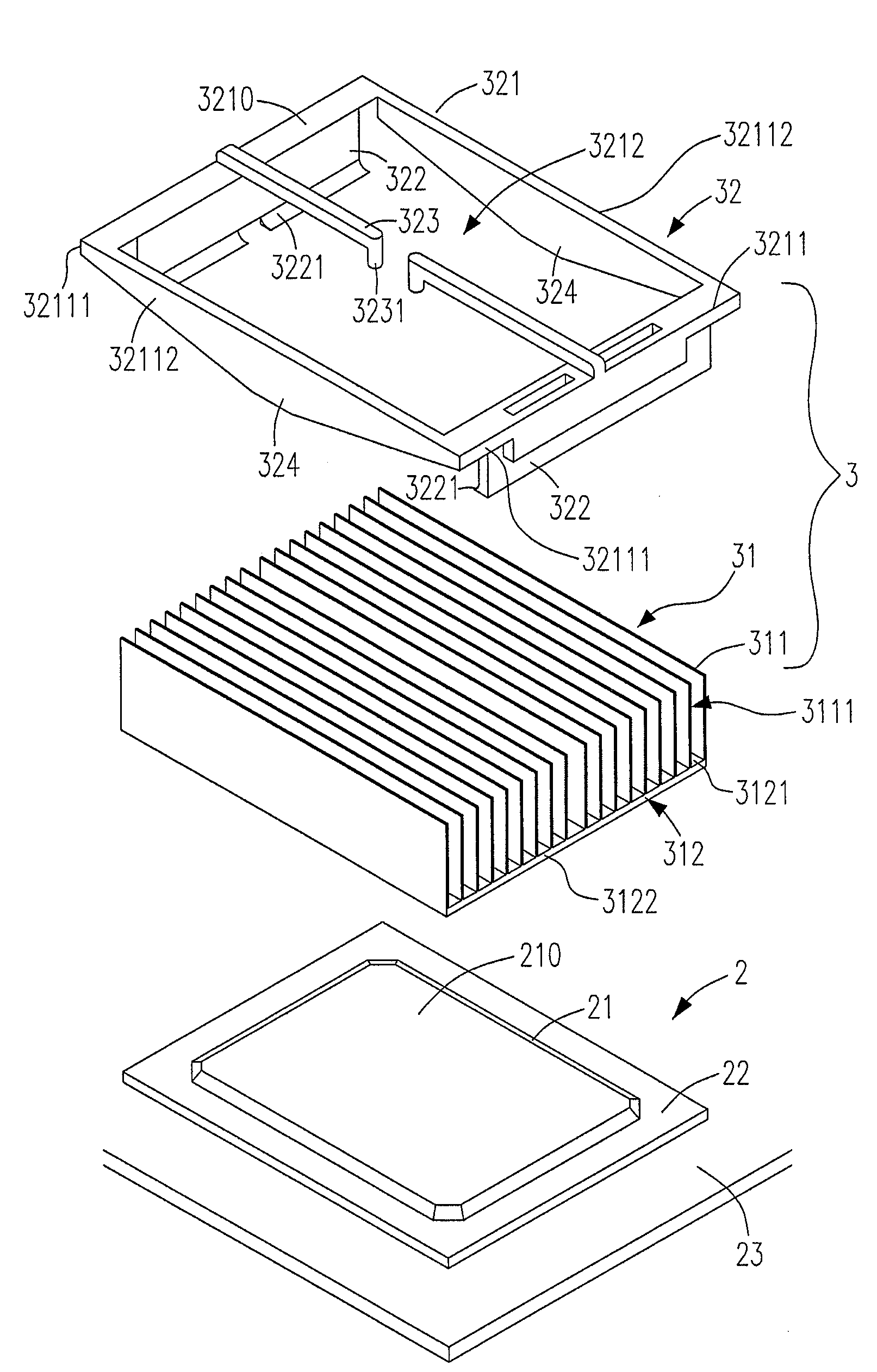
[0029]Please refer to FIG. 4, which shows an exploded perspective view of a preferred embodiment of the proposed heat sink assembly 3 having a heat sink 31 and a retaining device 32, which is employed to mount the heat sink 31 on a first top 210 of a chipset assembly 2 in the present invention. The chipset assembly 2 includes the first top 210, a chipset 21, a substrate 22 and a PC board 23. The heat sink 31 further includes a plurality of fins 311 and a base 312 having a top surface 3121 and a base plate 3122. The retaining device 32 further includes a frame 321 having a second top 3210, four side portions 3211 and a hole 3212 with a size larger than the base 312. The four side portions 3211 further include a first two and a second two opposite sides (32111 and 32112 respectively) and surround the hole 3212. The retaining device 32 further includes two retaining plates 322 each with a barb 3221 mounting the heat sink 31 on the first top 210 of the chipset assembly 2, two elastic ro...


PUM


Abstract

The proposed heat sink assembly mounted on a heat source includes a heat sink including a base with a top surface and a plurality of fins, and a retaining device including a frame with a top, a hole with a size larger than that of the base, an elastic rod connected with the frame, extending into the hole and having and end portion protruding towards the hole and pushing the heat sink and a plurality of retaining plates extending downwards from one of the first two and the second two opposite sides. Each of the retaining plates has a barb mounting the heat sink on the heat source and making the top surface raise through the hole to a same height of the top to facilitate the heat dissipation.

Description

FIELD OF THE INVENTION[0001]The present invention relates to a heat sink assembly including a heat sink and a retaining device and more particularly to a heat sink retaining device having a frame, which reaches the same height as that of a base of the heat sink when the heat sink is mounted on a heat source, to facilitate the heat dissipation.BACKGROUND OF THE INVENTION[0002]Nowadays, many electronic devices such as chipsets and RAMs would generate large amounts of heat during the operation. The heat must be removed efficiently. Otherwise, malfunction or damage may result. Due to the increasingly requirements in heat dissipation, various kinds of heat sink assemblies are proposed so as to dissipate the heat generated by the electronic devices more effectively.[0003]Please refer to FIG. 1, which is an exploded perspective view of a conventional heat sink assembly 1 having a heat sink 11 and a retaining device 12, which is employed to mount the heat sink 11 on a first top 210 of a chi...

Claims


Application Information

Patent Timeline
IPC IPC(8): H05K7/20F28D15/00
CPCH01L23/4093Y10T24/44026H01L2224/73253H01L2224/16
Inventor LIANG, ROBERT
Owner MALICO
Why Eureka
Try Eureka