Heat dissipating structure for computer casing

a computer and casing technology, applied in the direction of insulated conductors, electrical apparatus casings/cabinets/drawers, power cables, etc., can solve the problems of limiting the circulation of air through the openings, the inability to exhaust the heat generated by the electrical elements at the front and middle areas of the computer casing to the outside, and the inability to provide a superior heat dissipation efficiency of the computer casing, etc., to achieve improved heat dissip

Inactive Publication Date: 2005-10-27
SHUTTLE
View PDF1 Cites 8 Cited by
  • Summary
  • Abstract
  • Description
  • Claims
  • Application Information

AI Technical Summary

Benefits of technology

[0007] The present invention is to provide a heat dissipating structure for a computer casing. Through the heat dissipating openings mounted on the front board, the air flowing outside the rectangular hexahedron is drawn into the inside computer casing so that the heat generated by the electrical elements at the front and middle areas of the computer casing can be exhausted to the outside. Therefore, the moving energy of the air flowing inside the computer casing is enhanced and a better heat dissipating effectiveness is achieved.

Problems solved by technology

Therefore, how to provide a computer casing with a superior heat dissipating efficiency has become a major problem waited to be solved by the research workers in the industry.
However, the heat dissipating structure for the conventional computer casing still has the following problems in the practical implement:
That is, the heat generated by the electrical elements at the front and middle areas of the computer casing can not be exhausted to the outside through the former circulation of the air flowing.
Nevertheless, since there are many elements like memory modules, display card, and sound card inside the computer casing, or because the ambient environment where the computer host machine is located is limited (i.e. the lateral side of the casing is against the wall), the circulation of the air flowing through the openings has a certain limitation.

Method used


Image

  • Heat dissipating structure for computer casing
  • Heat dissipating structure for computer casing
  • Heat dissipating structure for computer casing

Examples


Embodiment Construction

[0015] The present invention will now be described more specifically with reference to the following embodiments. It is to be noted that the following descriptions of preferred embodiments of this invention are presented herein for purpose of illustration and description only; it is not intended to be exhaustive or to be limited to the precise form disclosed.

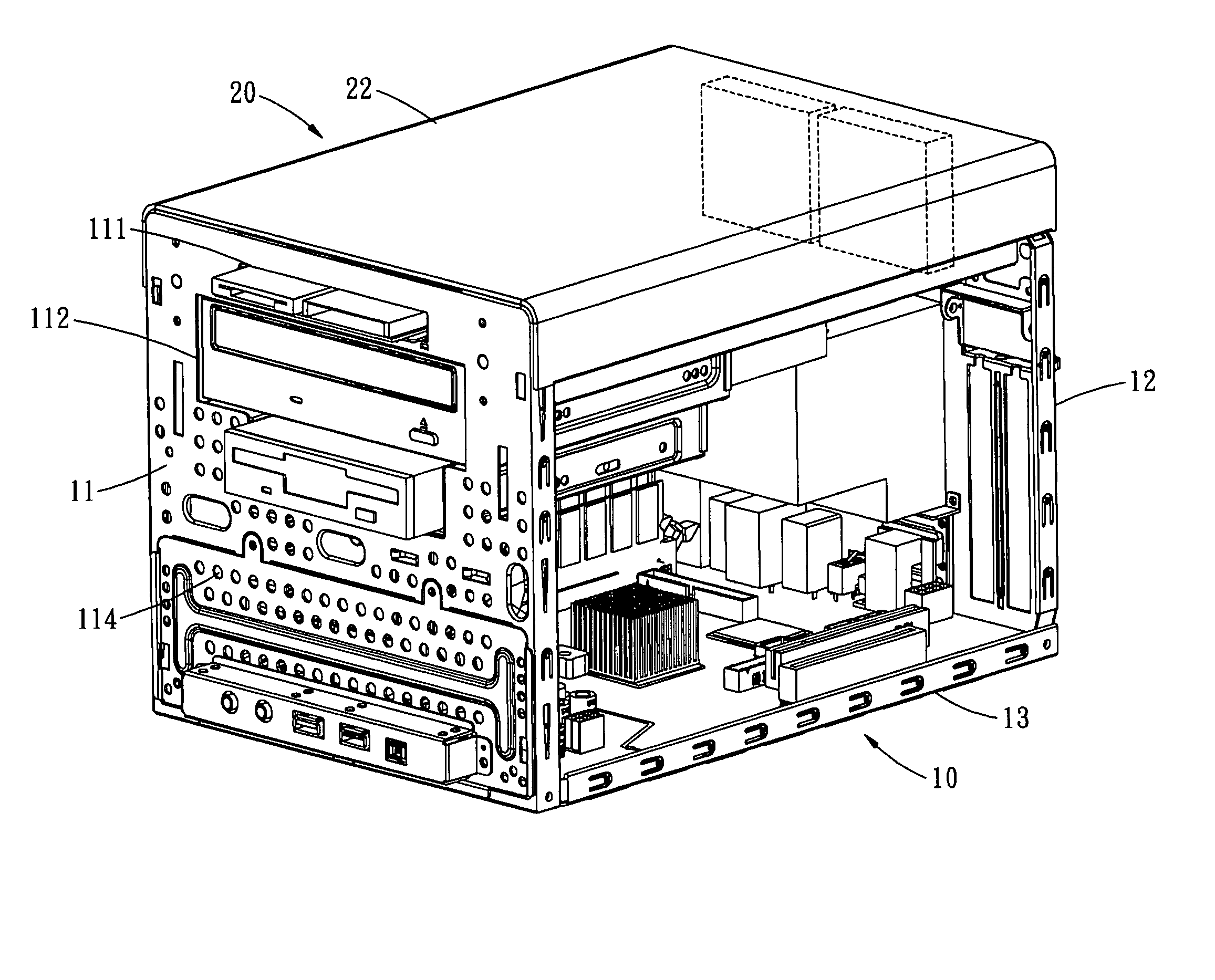
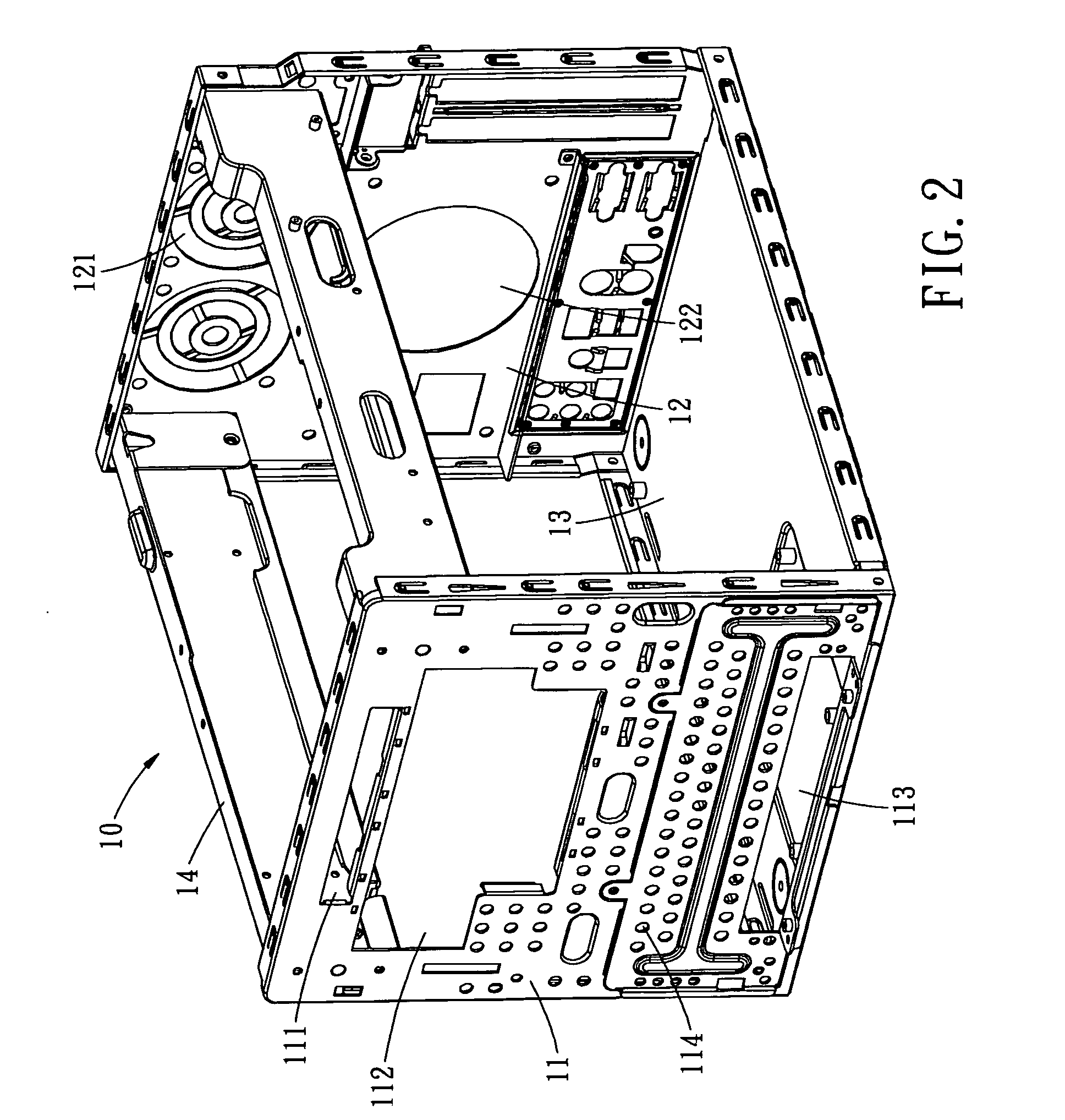
[0016] Please refer to FIG. 2 which shows the rectangular body of the computer casing according to a preferred embodiment of the present invention. The heat dissipating structure for a computer casing is provided in the present invention. The computer casing has the front board 11, the back board 12, the bottom board 13 and a pair of supporting frames 14. The front board 11 and the back board 12 are parallel to each other and correspond to each other by being connected together on the bottom board 13. There are two supporting frames 14 mounted at an opposite side corresponding to the bottom board 13. The two supporting frames 1...


PUM


Abstract

A heat dissipating structure for a computer casing includes a computer casing having a front board, a back board, and a bottom board, wherein the front board and the back board are parallel and correspond to each other by being connected together on the bottom board. There are two supporting frames mounted at an opposite side corresponding to the bottom board for respectively connecting with the upper sides of the front board and the back board so as to form a rectangular hexahedron. There are plural placing slots mounted on the front board for placing a disk drive, a CD-ROM drive, and plural connectors therein, wherein the front board further has the plural heat dissipating openings mounted thereon between the positions of the placing slots. Through the heat dissipating openings, the air flowing outside is drawn into the inside computer casing so that the heat generated by the electrical elements can be exhausted to the outside and a better heat dissipating effectiveness is achieved.

Description

BACKGROUND OF THE INVENTION [0001] The present invention is related to a heat dissipating structure, and more particularly, to a heat dissipating structure for a computer casing, which is able to increase the circulation of the air flowing inside the computer casing so that the heat generated by the electrical elements at the front board and inside the computer casing can be rapidly dissipated. Accordingly, a better heat dissipating effectiveness is achieved. With the fast and flourishing developments in the industry of information technology, the designs relevant to the computer field focuses on small, thinness, and lightness. Especially when the computer host machine is miniaturized, the working room for the user has become more spacious and comfortable. However, because the outside appearance and the volume of the computer host machine is significantly miniaturized and also the computer system is heading to the developing trend of high working speed and high frequency, the heat g...

Claims


Application Information

Patent Timeline
Patent Type & Authority Applications(United States)
IPC IPC(8): G06F1/20
CPCG06F1/20
Inventor CHEN, YIN-HUNG
Owner SHUTTLE
Why Eureka
Try Eureka