Disk drive device and address detection method with binarized push-pull signal

a drive device and push-pull signal technology, applied in the field of drive device and address detection method with binarized push-pull signal, can solve the problems of pattern waveform blur, and difficult to read land prepits lpp after information is recorded

Inactive Publication Date: 2007-12-11
SONY CORP
View PDF8 Cites 2 Cited by
  • Summary
  • Abstract
  • Description
  • Claims
  • Application Information

AI Technical Summary

Benefits of technology

[0016]In view of such circumstances, an object of the present invention is to be capable of satisfactorily detecting address information by land prepits even after data is recorded in a disk drive device.
[0019]According to the present invention described above, a push-pull signal is integrated in a period in which land prepits are detected by a window signal, and the land prepit signal is detected from the integrated result. In this case, the integration of the push-pull signal makes it possible to obtain a sharp waveform corresponding to the land prepit.

Problems solved by technology

However, after information is recorded in the grooves, which are recording tracks, the land prepits LPP become difficult to read as a result of interference by pits (phase change pits, etc.) formed in the grooves.
Furthermore, the land prepits LPP of the disk after information is recorded become difficult to read depending on the status of an optical pickup (recording / playback head), for example, variation of the position of the photodetector for detecting reflected light, and various kinds of aberrations.
However, when data is recorded in the groove tracks, as shown in FIG. 5C, the eye pattern waveform blurs, and the detection of “1” or “0” as b2, b1, and b0 of the land prepits LPP becomes difficult.
As a result, the address error rate is deteriorated.
The fact that, after the data is recorded, the address reading by the land prepits LPP becomes difficult in this manner means that, for example, when additional recording is performed on a disk after recording or when a seek is performed, the address cannot be obtained satisfactorily, and the operation performance decreases.
In that case, selection of the pickup to be incorporated and use of an expensive pickup with high accuracy become necessary, resulting in an undesirable cost increase of the disk drive device.

Method used


Image

  • Disk drive device and address detection method with binarized push-pull signal
  • Disk drive device and address detection method with binarized push-pull signal
  • Disk drive device and address detection method with binarized push-pull signal

Examples


Embodiment Construction

[0026]An embodiment of the present invention will be described below by using as an example a disk drive device (recording / playback device) compatible with DVD-Rs and DVD-RWs.

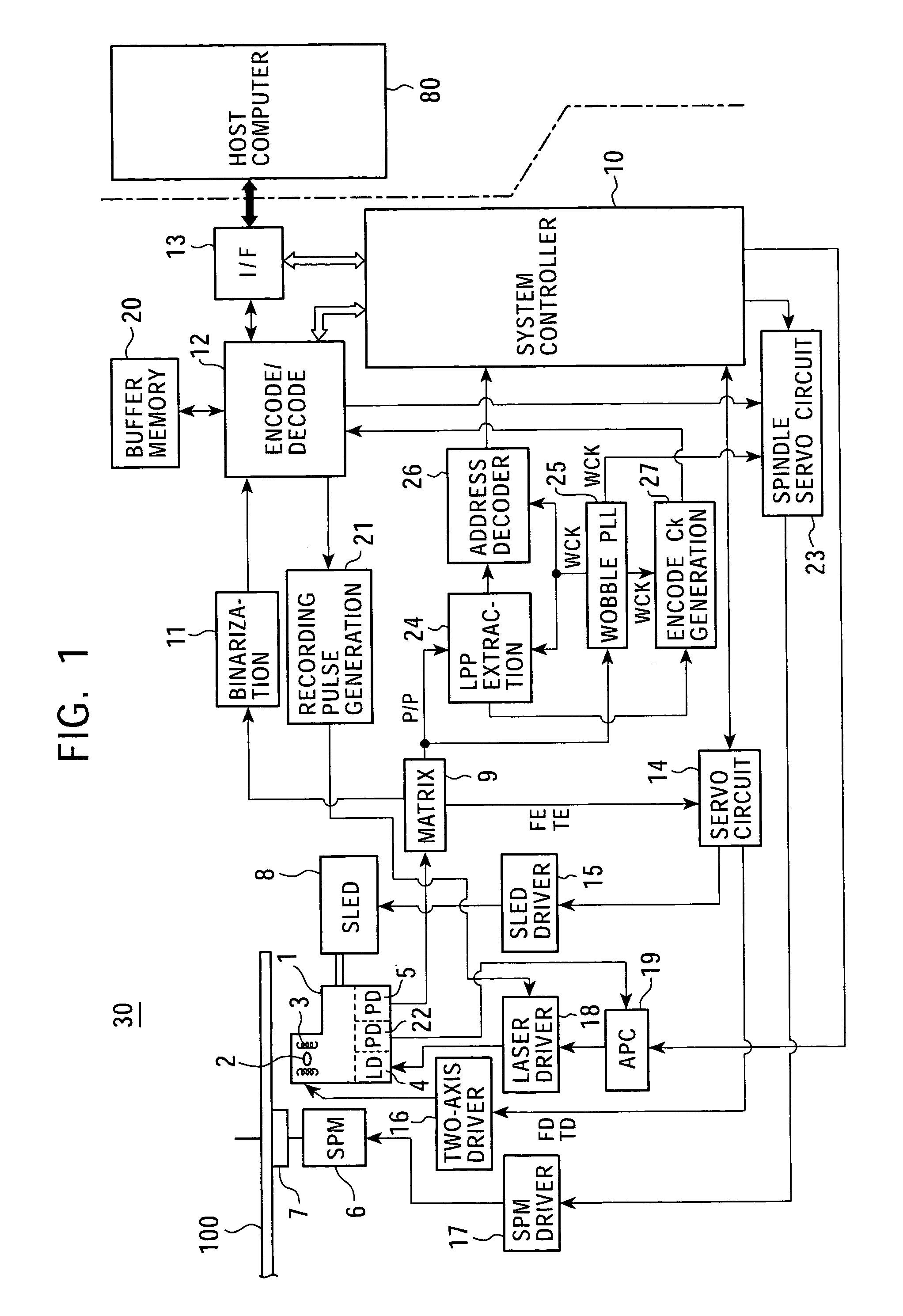
[0027]FIG. 1 shows the configuration of a disk drive device 30 of this example.

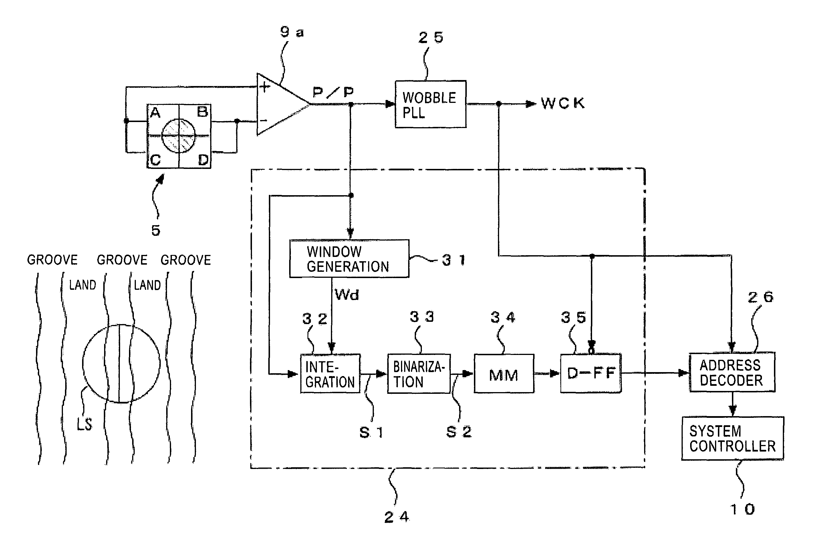
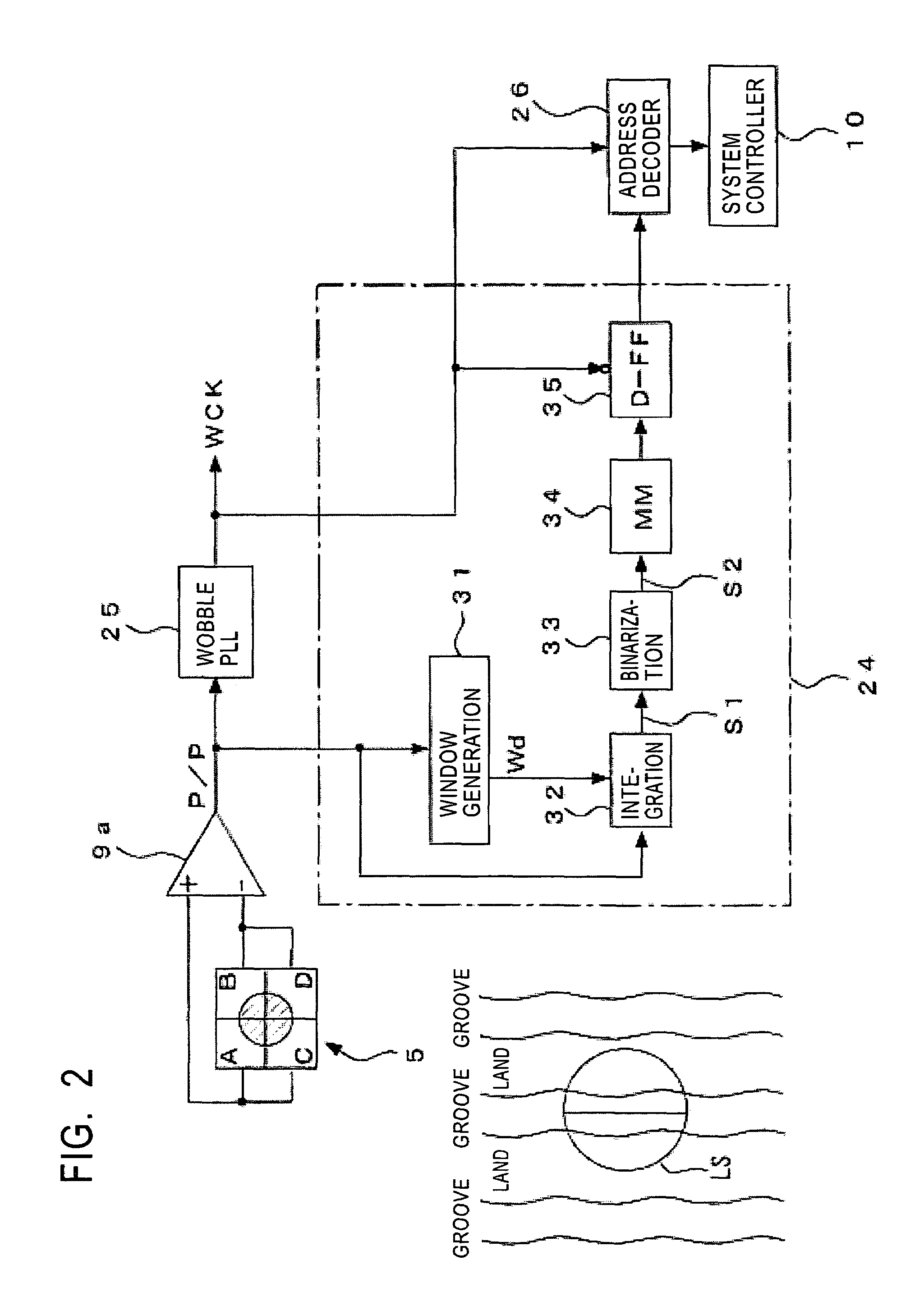
[0028]A disk 100 as a DVD-R or a DVD-RW is placed on a turntable 7, and is rotationally driven by a spindle motor 6 at a constant linear velocity (CLV) during a recording / playback operation. Then, an optical pickup 1 reads pit data recorded on tracks (groove tracks) on the disk 100, wobbling information of tracks, and land prepit information. The pits recorded as data on tracks formed as grooves are so-called pigment change pits or phase change pits.

[0029]Inside the pickup 1, a laser diode 4 serving as a laser light source; a photodetector 5 for detecting reflected light; an objective lens 2, which becomes the output end of the laser light; and an optical system (not shown) for radiating laser light onto the disk recording surface vi...


PUM

PropertyMeasurementUnit
wavelengthaaaaaaaaaa
threshold levelaaaaaaaaaa

Abstract

A disk drive device capable of satisfactorily detecting address information recorded by land prepits even after data is recorded is provided. When address information recorded by land prepits is detected from a disk on which lands and grooves as recording tracks are formed and address information is recorded as land prepits on the lands, a window signal is generated by binarizing a push-pull signal (window generation circuit 31), the push-pull signal is integrated in a period based on the window signal (integration circuit 32), and the address information by the land prepits is extracted from the integrated signal (33, 34, 35, and 26).

Description

TECHNICAL FIELD[0001]The present invention relates to a disk drive device for performing recording and playback to and from a disk recording medium such as an optical disk, and to an address detection method therefor.BACKGROUND ART[0002]In order to record data on a disk, means for performing guidance for forming data tracks becomes necessary. For this reason, it has been practiced that grooves are formed in advance as pregrooves, and the grooves or lands (parts whose cross sections are shaped as a plateau, sandwiched between grooves) are used as data tracks.[0003]Also, there is a need to record address information so that data can be recorded at a predetermined position on the data tracks. This address information is recorded by causing grooves to wobble (meander) or by forming prepits on the data tracks.[0004]For example, among DVDs (Digital Versatile Discs), in DVD-RWs, which are rewritable disks using a phase change recording method, and DVD-Rs, which are recordable disks using a...

Claims


Application Information

Patent Timeline
Patent Type & Authority Patents(United States)
IPC IPC(8): G11B5/09G06F13/00G11B20/10G11B7/005G11B7/007G11B7/09G11B20/12G11B20/14G11B27/19G11B27/24H04N7/173
CPCG11B7/0053G11B7/00718G11B20/1403G11B27/24G11B20/10G11B7/00745G11B7/0901G11B7/24082G11B2220/2562G11B2220/216G11B2220/218G11B7/007G11B7/005
Inventor IIMURA, SHINICHIRO
Owner SONY CORP
Why Eureka
Try Eureka