Optical pickup

a pickup and optical technology, applied in the field of optical pickups, can solve the problems of error signal quality deterioration, difficult to make such adjustments for each laser beam emitted from the multi-laser source unit, etc., and achieve the effect of satisfying the detection of focus and tracking error signals

Inactive Publication Date: 2012-03-01
HITACHI MEDIA ELECTORONICS CO LTD
View PDF6 Cites 2 Cited by
  • Summary
  • Abstract
  • Description
  • Claims
  • Application Information

AI Technical Summary

Benefits of technology

[0009]The present invention has been made in view of the above circumstances, and it is an object of the invention to provide an optical pickup which, including a multi-laser source unit, is compatible with multiple recording media and realizes, by preventing quality deterioration of the focus and tracking error signals caused by relative shifting between laser beams, satisfactory detection of the focus and tracking error signals by a one-beam method in a simply structured optical system.
[0013]According to the present invention, a multi-media compatible optical pickup including a multi-laser source unit enables satisfactory detection of focus and tracking error signals using a one-beam method in a simply structured optical system.

Problems solved by technology

When a multi-media compatible optical pickup like the one described above including a multi-laser source unit and common optical parts, e.g. a lens and a beam splitter, for multiple media is used, however, it is extremely difficult to make such adjustment for each laser beam emitted from the multi-laser source unit.
When a one-beam method is used to detect a focus error signal and a tracking error signal, relative shifting between laser beams is a major cause of error signal quality deterioration.

Method used


Image

  • Optical pickup
  • Optical pickup
  • Optical pickup

Examples


Embodiment Construction

[0027]An embodiment of the present invention will be described below with reference to drawings.

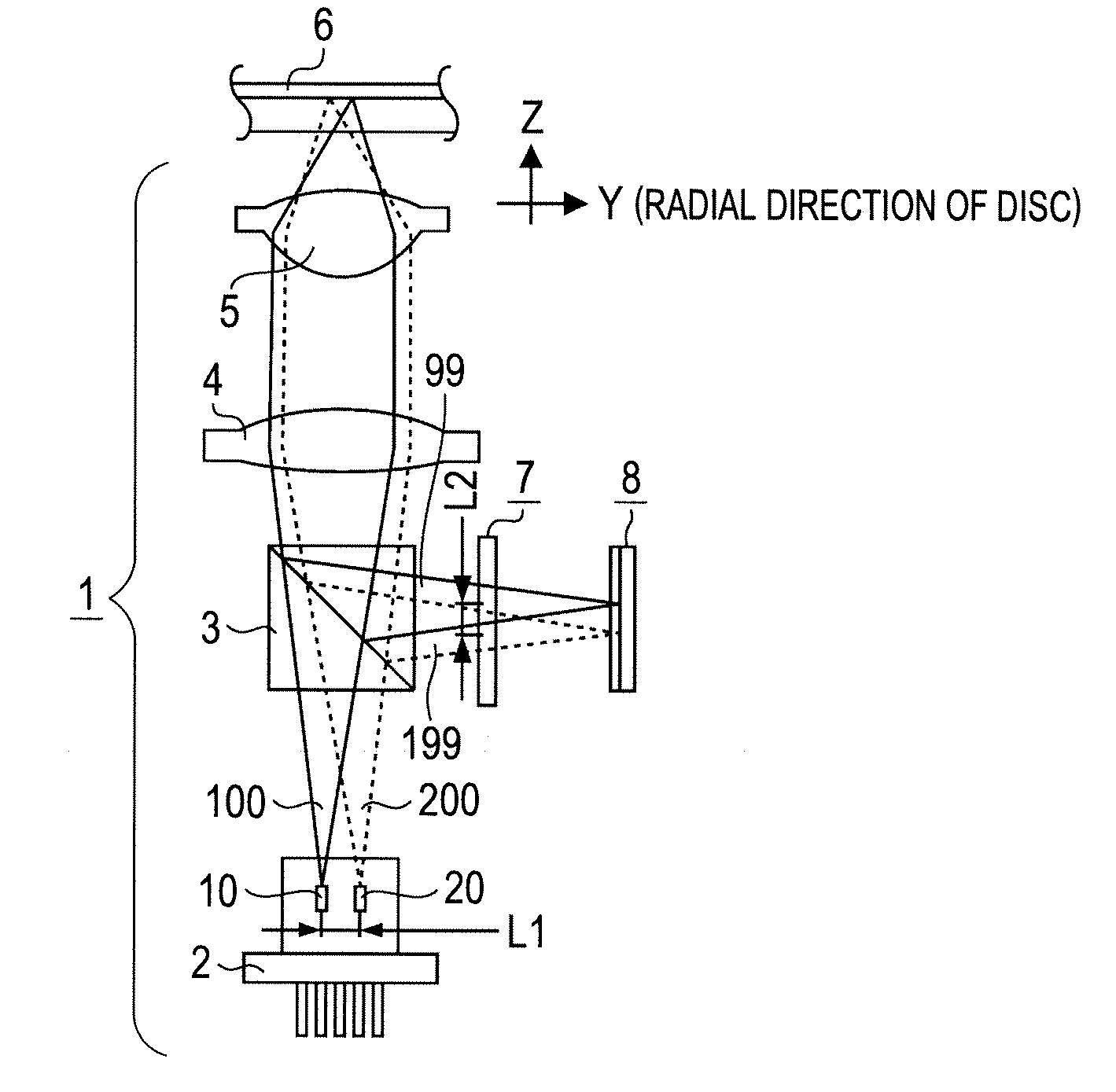
[0028]FIG. 1 shows approximate parts arrangement in an optical system of an optical pickup according to an embodiment of the present invention.

[0029]An optical pickup 1 includes a multi-laser source unit 2 housing both a semiconductor laser chip 10 which emits a laser beam with a wavelength of 650 to 660 nm used for DVD recording or reproduction and a semiconductor laser chip 20 which emits a laser beam with a wavelength of 780 to 790 nm used for CD recording or reproduction. When recording or reproducing information on or from a DVD, the semiconductor laser chip 10 lights and emits a divergent laser beam 100. When recording or reproducing information on or from a CD, the semiconductor laser chip 20 lights and emits a divergent laser beam 200. The semiconductor laser chip 10 used for DVD recording / reproduction (hereinafter referred to as the “semiconductor laser chip 10 for DVD”) and the ...


PUM

PropertyMeasurementUnit
wavelengthaaaaaaaaaa
wavelengthsaaaaaaaaaa

Abstract

An optical pickup compatible with two wavelengths such as an optical pickup having a two-wavelength, multi-laser source unit to be compatible with both DVDs and CDs prevents, in a simply structured optical system, error signal quality deterioration caused by relative shifting between laser beams and realizes detection of focus and tracking error signals. The optical system is provided with an optical waveguide device and a photodetector. The optical waveguide device includes a holographic diffraction grating having three regions divided by two approximately parallel division lines which extend respectively passing the optical axes of a laser beam for DVD and a laser beam for CD. The photodetector has plural light receiving surfaces each divided into three regions. This allows reliable focus and tracking error signals to be detected during both DVD reproduction and CD reproduction.

Description

INCORPORATION BY REFERENCE[0001]This application relates to and claims priority from Japanese Patent Application No. 2010-193268 filed on Aug. 31, 2010, the entire disclosure of which is incorporated herein by reference.BACKGROUND OF THE INVENTION[0002](1) Field of the Invention[0003]The present invention relates to an optical pickup including plural laser sources and being capable of reproducing information signals recorded on plural types of optical information recording media.[0004](2) Description of the Related Art[0005]In recent years, optical pickups each usable as a multi-media compatible optical pickup capable of recording or reproducing information on or from plural types of optical information recording media (hereinafter referred to as “optical discs” for simplification) using mutually different wavelengths, for example, DVDs and CDs, or BDs and DVDs have come into use. Such optical pickups each have a multi-laser source unit including plural semiconductor laser chips whi...

Claims


Application Information

Patent Timeline
Patent Type & Authority Applications(United States)
IPC IPC(8): G11B7/135
CPCG11B7/0912G11B7/1381G11B7/094
Inventor OHNISHI, KUNIKAZUYAMAZAKI, KAZUYOSHINAGASAWA, MITSURU
Owner HITACHI MEDIA ELECTORONICS CO LTD
Why Eureka
Try Eureka