Method for allocating protection bandwidth in a telecommunications mesh network

Inactive Publication Date: 2007-12-11
TELLABS OPERATIONS
View PDF6 Cites 107 Cited by
  • Summary
  • Abstract
  • Description
  • Claims
  • Application Information

AI Technical Summary

Benefits of technology

[0012]From the foregoing, it may be appreciated by those skilled in the art that a need has arisen for an ability to provide protection path in a mesh network with fast protection switching capabilities. In accordance with the present inv

Problems solved by technology

One weakness of p-cycles is that maximum bandwidth efficiency is achieved with large p-cycles, and if traffic demands are arriving gradually over time, then the carrier must choose between allocati

Method used


Image

  • Method for allocating protection bandwidth in a telecommunications mesh network
  • Method for allocating protection bandwidth in a telecommunications mesh network
  • Method for allocating protection bandwidth in a telecommunications mesh network

Examples


Embodiment Construction

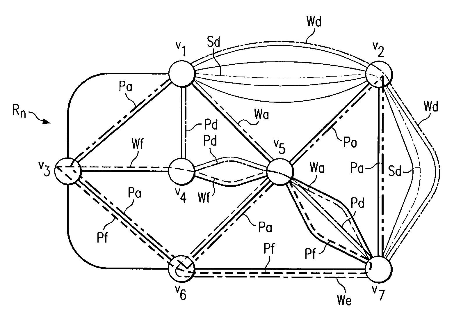
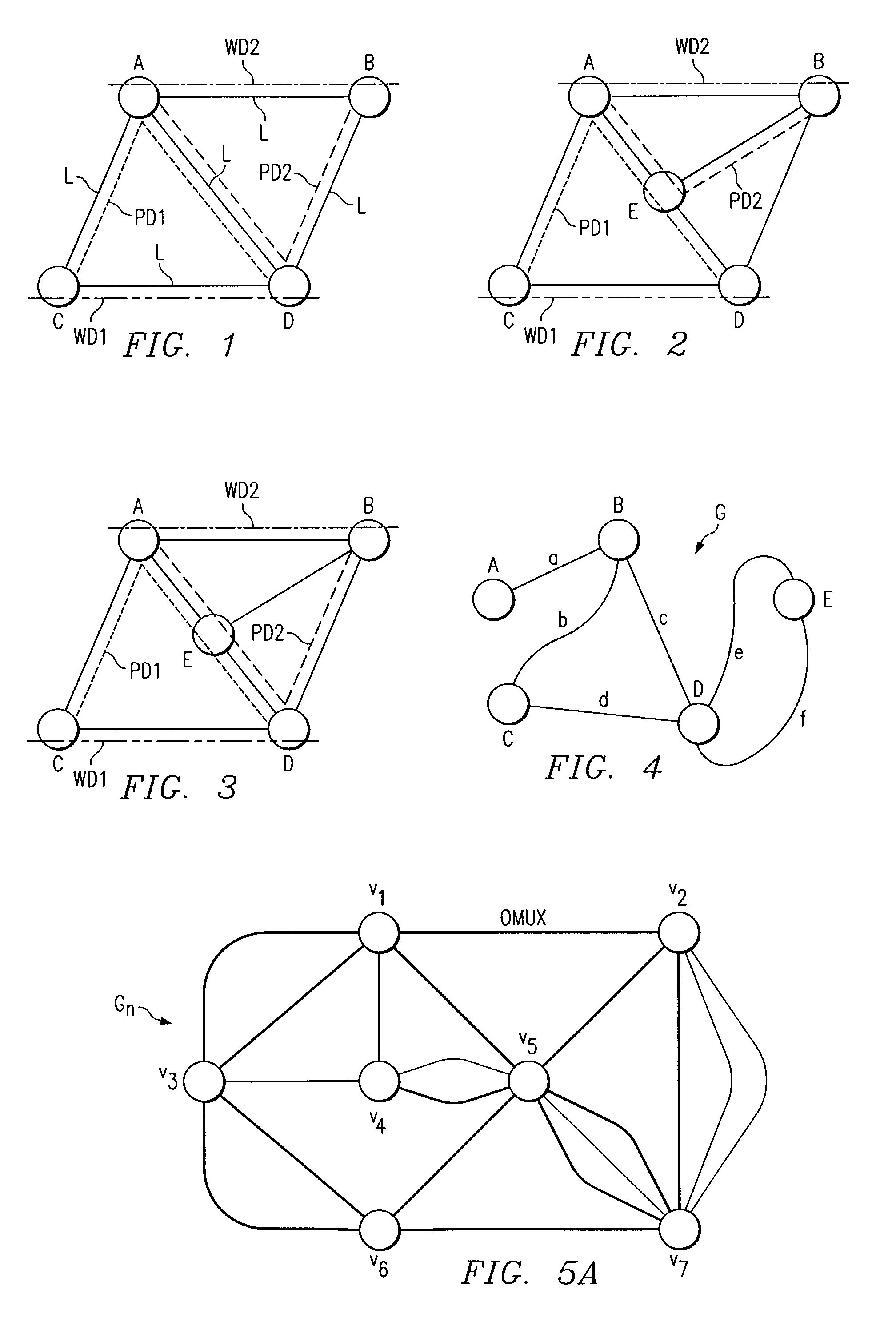
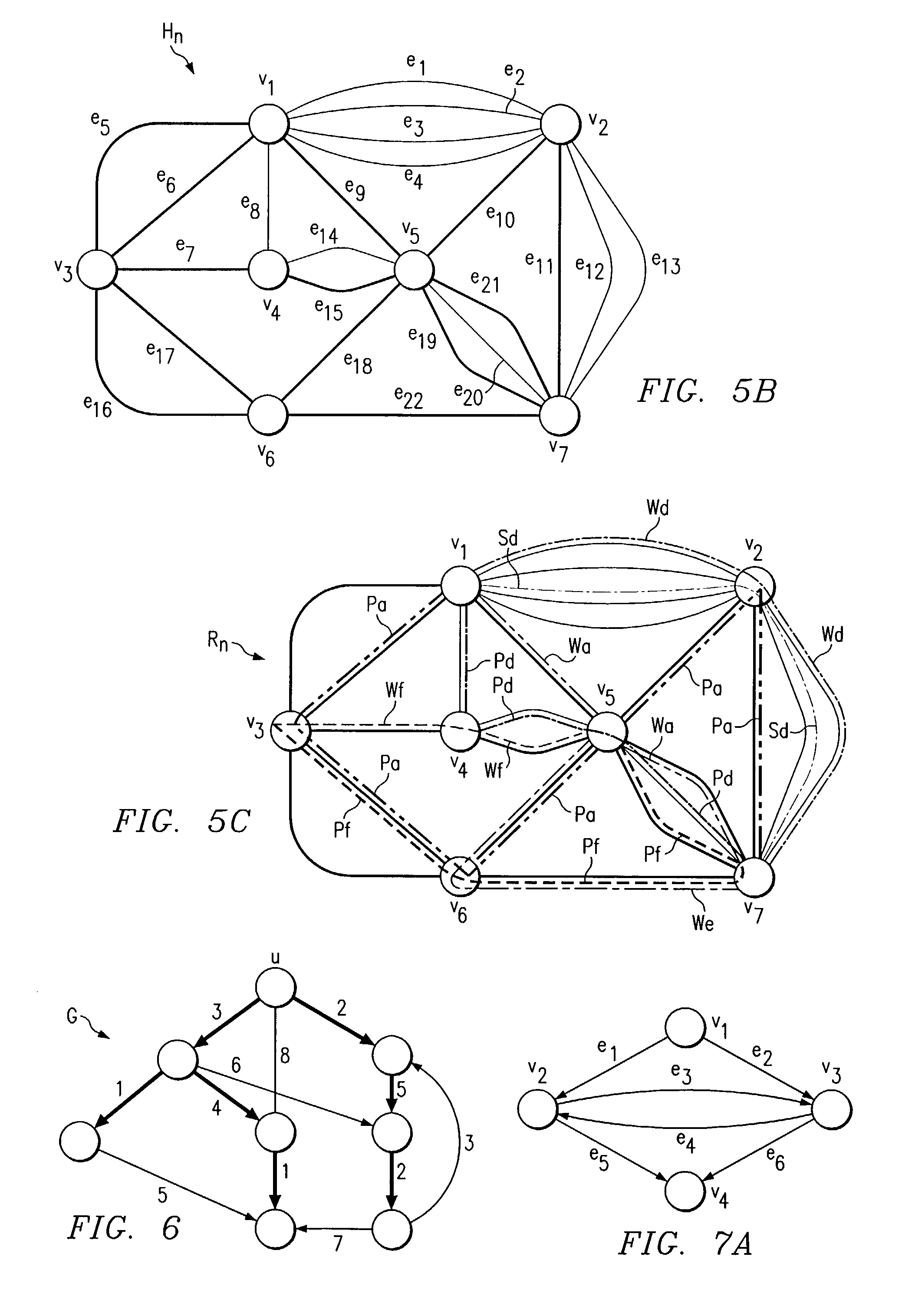
[0032]FIG. 3 is an example of an arbitrary mesh shared path-based protection telecommunications network 10. Telecommunications network includes a collection of geographically dispersed network elements, called nodes ABCDE, connected by communication links e (e.g., fiber, wireless links). The topology of the telecommunications network 10 may be represented by an undirected graph G. In operation, successive requests are made for a bi-directional demand D1 to be routed between two nodes C and D and a bi-directional demand D2 to be routed between nodes A and B in graph G. After a request is received, two interior-disjoint paths need to be allocated for each demand: a working path WD1 / WD2 and a protection path PD1 / PD2. The purpose of protection path PD1 and PD2 is to route the requested demand in case of a single network failure in working path WD1 or WD2. Working paths WD1 and WD2 need to allocate dedicated bandwidth while protection paths PD1 and PD2 do not, i.e., it can be shared amon...


PUM


Abstract

A telecommunications mesh network includes a plurality of nodes each interconnected by an edge. A traffic demand is received having a working path with a link of edges interconnecting a source node with a destination node. The telecommunications mesh network has one or more pre-cross-connected trails associated therewith that are subdivided into one or more subtrails. Subtrails that do not meet pre-determined conditions are discarded. A logical graph representation of the telecommunications mesh network is created from subtrails that have not been discarded. Unused, shortcut, and rival edges are inserted into the logical graph. A shortest admissible protection path from the source node to the destination node is identified from the logical graph.

Description

RELATED APPLICATIONS[0001]The present application claims the benefit of Provisional Application No. 60 / 291,508 filed May 16, 2001.TECHNICAL FIELD OF THE INVENTION[0002]The present invention relates in general to telecommunications network design and more particularly to a method for allocating bandwidth in a telecommunications mesh network.BACKGROUND OF THE INVENTION[0003]Modern optical networks carry large amounts of traffic, so it is imperative that they be able to survive an accidental failure such as a fiber cut or a node failure. The simplest way to protect a light path against failures is to employ 1+1 or dedicated protection. That is, in addition to the primary or working path, one allocates a secondary or protection path and transmits a duplicate copy of the traffic along the protection path. If there is a failure on the working path, then one switches to the protection path.[0004]FIG. 1 shows an example of a square mesh network. The square mesh network may have four nodes A...

Claims


Application Information

Patent Timeline
IPC IPC(8): H04B10/20
CPCH04L45/02H04L45/12H04L45/22H04L43/0811H04Q11/0062H04L45/28H04Q2011/0081
Inventor CHUDAK, FABIAN A.FFRENCH, ANTHONY M.CHOW, TIMOTHY Y.
Owner TELLABS OPERATIONS
Why Eureka
Try Eureka