Centrifugal oil separator in an internal combustion engine

a centrifugal oil separator and internal combustion engine technology, applied in the direction of machines/engines, gymnasiums, constructions, etc., can solve the problems of relative high installation costs, and achieve the effects of low weight, low centrifugal forces, and high retention forces

Inactive Publication Date: 2007-12-18
DAIMLER AG
View PDF10 Cites 21 Cited by
  • Summary
  • Abstract
  • Description
  • Claims
  • Application Information

AI Technical Summary

Benefits of technology

[0007]The centrifuge housing and the metal bushing form a pre-manufactured unit which is slipped onto the shaft and is connected to the latter. The metal bushing is capable of transmitting high retaining forces, with the result that a secure fastening on the centrifuge shaft is possible. The plastic centrifuge housing is distinguished by a low weight, resulting in relatively low centrifugal forces in the housing wall during rotation of the oil separator.
[0008]For easier installation, the metal bushing can be slipped onto the centrifuge shaft with little play; forces which occur during the operation are readily accommodated by the metal bushing and the centrifuge housing is not subjected to these forces, as a result of which improved rotatability and a longer service life are ensured.

Problems solved by technology

However, this involves relatively high installation expenses.

Method used


Image

  • Centrifugal oil separator in an internal combustion engine
  • Centrifugal oil separator in an internal combustion engine
  • Centrifugal oil separator in an internal combustion engine

Examples


Embodiment Construction

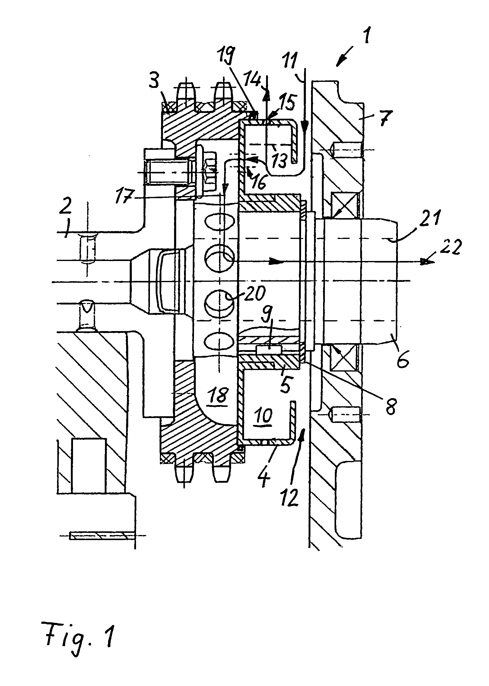
[0016]In the following figures, identical components are designated by the same reference numerals.

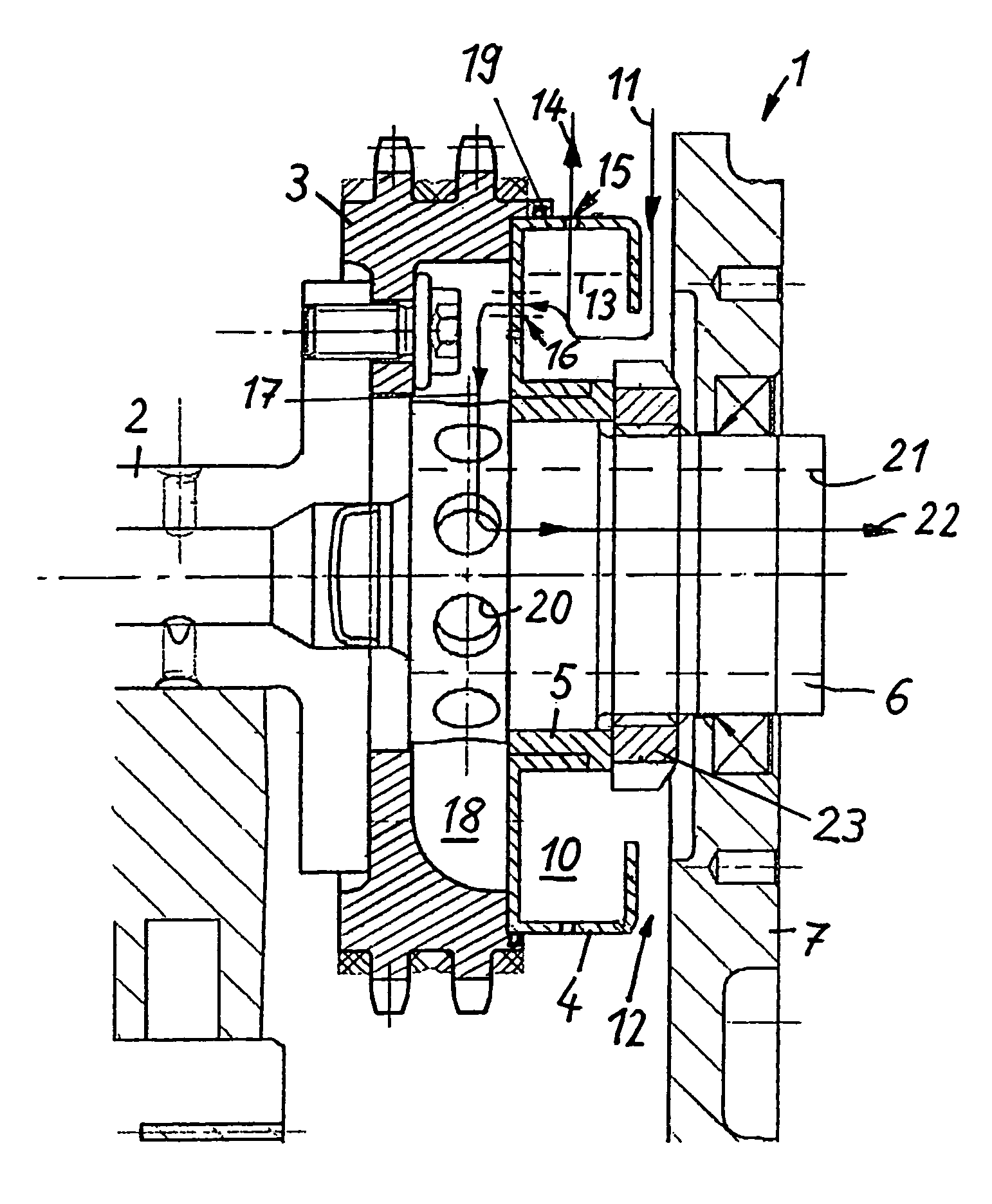
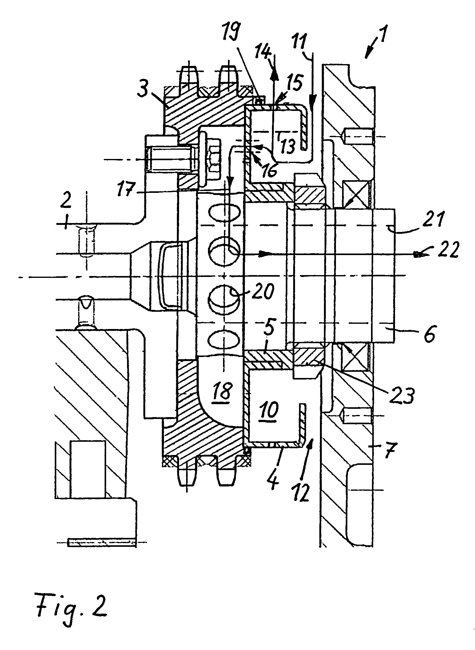
[0017]The centrifugal oil separator 1 which is illustrated in FIG. 1 is connected in a rotationally fixed manner to a camshaft 2 of an internal combustion engine and is arranged at an end face of a chain wheel 3 which is flange-mounted onto the camshaft 2 for rotation therewith. The oil separator 1 comprises a centrifuge housing 4 which is manufactured from plastic, and a metal bushing 5 which is integrated into the centrifuge housing 4 and forms the hub of the centrifuge housing. Furthermore, the oil separator 1 comprises a centrifuge shaft 6 which is inserted into the metal bushing 5.

[0018]The metal bushing 5 is secured both in the circumferential direction and also axially against being unintentionally released from the centrifuge shaft 6. A securing ring 8 is provided for the axial securing, which ring can be inserted into an encircling groove on the centrifuge shaft 6 and is there...


PUM

PropertyMeasurementUnit
centrifugal forcesaaaaaaaaaa
retaining forcesaaaaaaaaaa
weightaaaaaaaaaa

Abstract

In a centrifugal oil separator in an internal combustion engine including a centrifuge housing which is placed in a rotationally fixed manner onto a rotating centrifuge shaft, the centrifuge housing is manufactured from plastic and a metal bushing is integrated into the centrifuge housing and is slipped onto the centrifuge shaft.

Description

[0001]This is a Continuation-In-Part Application of International application PCT / EP03 / 04308 filed Apr. 25, 2003 and claiming the priority of German application 102 26 695.6 filed Jun. 15, 2002.BACKGROUND OF THE INVENTION[0002]The invention relates to a centrifugal oil separator in an internal combustion engine including a centrifuge housing.[0003]Such a centrifugal oil separator is described, for example, in DE 196 07 919 A1. This oil separator can be used to separate oil particles in an oil / air mixture in a crankcase of an internal combustion engine and to return the oil to the oil sump. The centrifugal oil separator makes use of rotation generating centrifugal forces to separate the oil particles from the mixture and conduct the oil away. The oil separator has a centrifuge housing including a separating space in which baffles are arranged for collecting the oil particles. The oil collected is removed radially and the cleaned air is conducted away axially via an outflow passage in...

Claims


Application Information

Patent Timeline
Patent Type & Authority Patents(United States)
IPC IPC(8): F01M13/04F01M1/00
CPCF01M13/04F01M2013/0422
Inventor BERGER, ALEXANDERNOLL, ROLANDRECKZUGEL, CHRISTOPHSCHMIDT, TIMO
Owner DAIMLER AG
Why Eureka
Try Eureka