System for undersea digital acoustic communications

Inactive Publication Date: 2007-12-18
NAVY UNITED STATES OF AMERICA AS REPRESENTED BY THE DEPT OF
View PDF7 Cites 24 Cited by
  • Summary
  • Abstract
  • Description
  • Claims
  • Application Information

AI Technical Summary

Benefits of technology

[0015]Another object of this invention is to provide an acoustic bi-directional undersea communication system that overcomes many of the problems of multi-path effects.
[0016]Still another object of this invention is to provide an acoustic undersea bi-directional c

Problems solved by technology

However, such systems tend to be complex and difficult to implement.
They also make certain assumptions about transmissions that may not be accurate in an actual ope

Method used


Image

  • System for undersea digital acoustic communications
  • System for undersea digital acoustic communications
  • System for undersea digital acoustic communications

Examples


Example

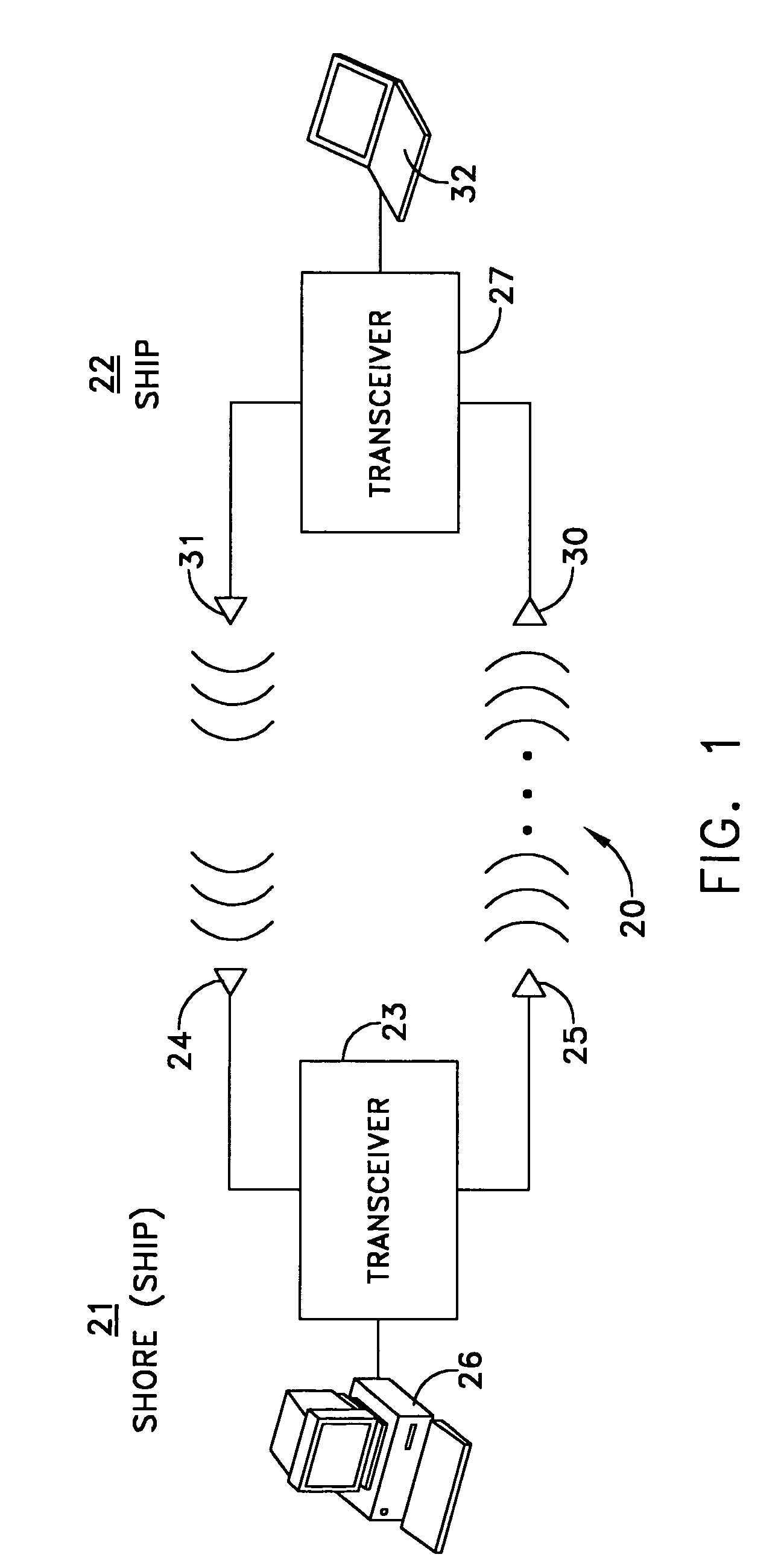
[0028]FIG. 1 depicts a communications system 20 constructed in accordance with this invention that establishes communications between two sites 21 and 22. Site 21 typically is a shore site, although it can be an offshore site as on a surface or other ship. Site 22 is a ship site, typically at a submarine or other undersea vehicle.

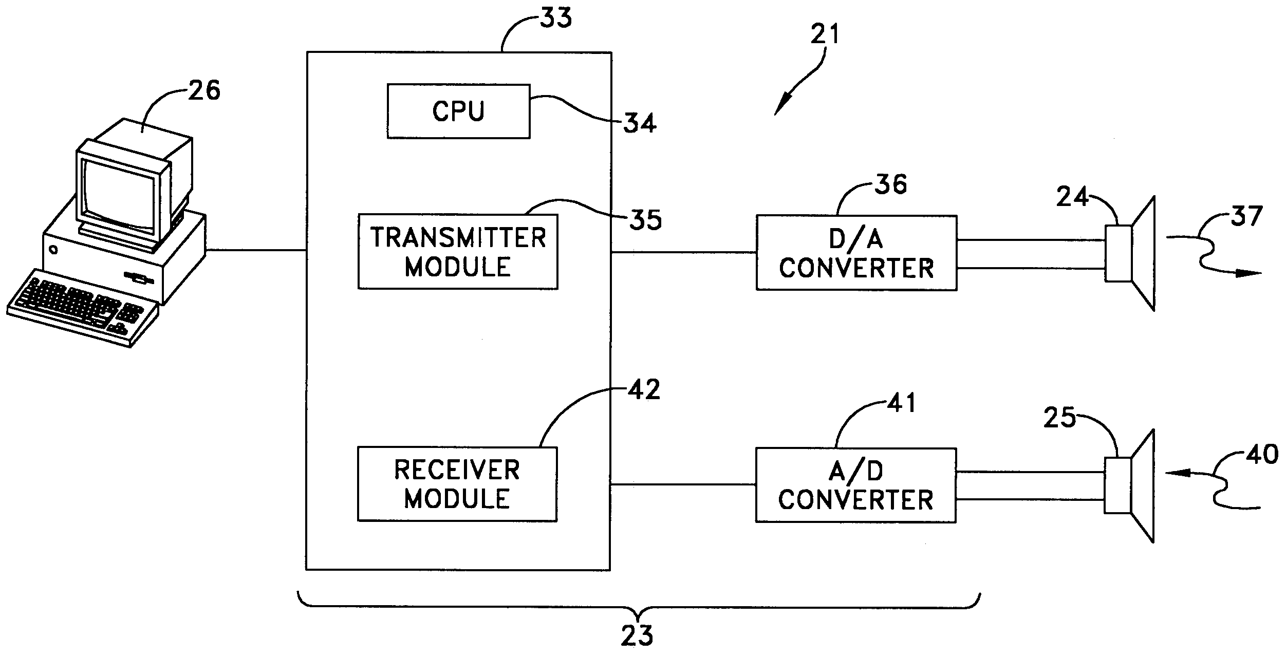
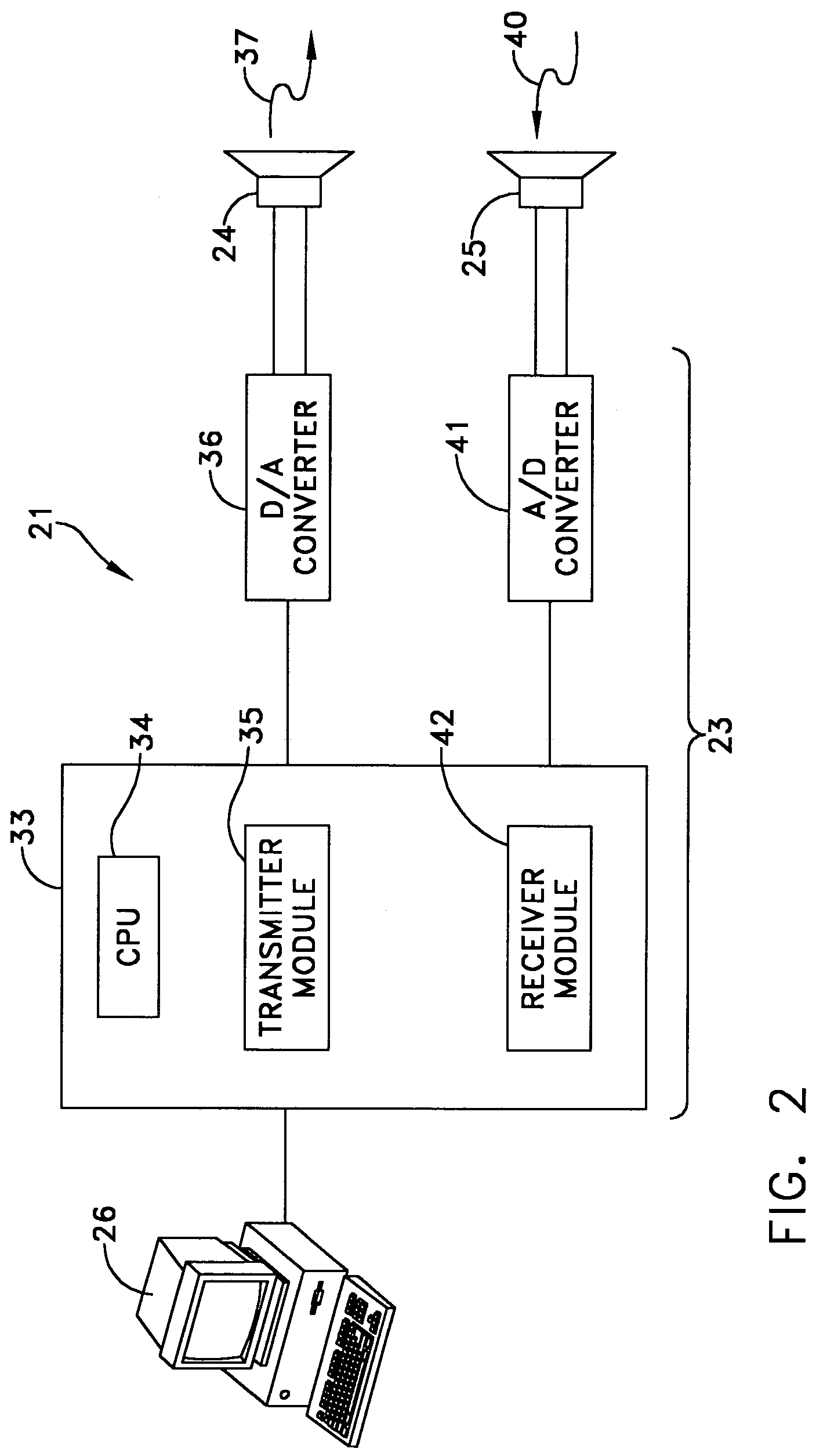
[0029]In this specific embodiment the shore site 21 includes a transceiver 23 that receives inputs from a receiving acoustic transducer 24 and that transmits acoustic signals from a transmitting acoustic transducer 25. The transceiver 23 is computer-based and transmits signals in response to messages input at a terminal 26 and displays messages on that same terminal 26.

[0030]Site 22 has a similar organization with a transceiver 27 that receives signals from a receiving acoustic transducer 30 and transmits signals from a transmitting acoustic transducer 31. A terminal 32 serves as an input device for messages to be transmitted and a display for received mess...


PUM


Abstract

An undersea communications system in which a message is converted to a redundant fixed-length data packet and transmitted acoustically as a quadrature phase-keyed signal in a frequency band with a continuous pilot signal at a frequency closely adjacent to the frequency band. A receiver uses the received continuous pilot signal to Doppler compensate the incoming quadrature phase keyed signal by estimating any Doppler distortion in the received pilot signal. The resultant redundant signals are then robustly processed coherently and jointly by the adaptive decision feedback equalizer and decoder to provide the original transmitted data.

Description

STATEMENT OF GOVERNMENT INTEREST[0001]The invention described herein may be manufactured and used by or for the Government of the United States of America for governmental purposes without the payment of any royalties thereon or therefore.BACKGROUND OF THE INVENTION[0002](1) Field of the Invention[0003]This invention generally relates to bi-directional communication systems and more specifically to communication systems capable of conducting bi-directional communications in an undersea environment.[0004](2) Description of the Prior Art[0005]Acoustic communications in undersea applications are subject to multi-path effects in the water. Multi-path effects are produced by acoustic propagations from a transmission point that travel either directly to an underwater receiver or may reflect from the ocean surface and ocean floor or even areas of different temperature and density to create cancellation and distortion of the directly propagated transmission.[0006]Some suggest that these mul...

Claims


Application Information

Patent Timeline
IPC IPC(8): H04B11/00
CPCH04B13/02H04B11/00
Inventor JARVIS, SUSAN M.BLACKMON, FLETCHER A.MORRISSEY, RONALD R.PENDERGRASS, NIXONSMITH, DEAN J.FITZPATRICK, KEVIN C.
Owner NAVY UNITED STATES OF AMERICA AS REPRESENTED BY THE DEPT OF
Why Eureka
Try Eureka