Station for withdrawing and erecting flat folded tubular blanks

a flat folded, blank technology, applied in the direction of packaging goods, paper/cardboard containers, box making operations, etc., can solve the problems of increased jamming possibility, prolonged downtime of machines, and necessity of testing and adjustment fine tuning

Active Publication Date: 2007-12-25
MARCHESINI GROUP SPA
View PDF23 Cites 24 Cited by
  • Summary
  • Abstract
  • Description
  • Claims
  • Application Information

AI Technical Summary

Benefits of technology

[0013]The object of the present invention is to propose a station for withdrawing flat folded blanks and for erecting thereof, in which the operating means are made in such a way, as to positively open the box and to maintain always controlled the arrangement of the box sides, until the box is inserted into a corresponding seat made on the box conveying line, thus avoiding the above mentioned disadvantages.
[0014]Another object of the present invention is to propose a station, in which it is possible to withdraw and erect blanks of dimensions varying from a minimum size to maximum size within a wide acceptable range, ensuring a reliable operation, particularly when the height of box edge-resting sides changes.
[0015]A further object of the present invention relates to the need for rapid adjustments of the work means in the proposed station, due to the box size changeover, without jeopardizing the operation reliability of the whole machine.

Problems solved by technology

The drawbacks of this technical solution result from a certain difficulty in setting the position of various fixed stop elements, to minimize the blank elastic return, when it is placed on the additional conveying line.
The obvious consequences of the above mentioned drawback are the machine prolonged downtimes at size changeover, the necessity of tests and adjustment fine tuning, as well as the increase of the jamming possibility, in particular during the passage between the additional conveying line and the box conveying line, if the boxes are not correctly squared.

Method used


Image

  • Station for withdrawing and erecting flat folded tubular blanks
  • Station for withdrawing and erecting flat folded tubular blanks
  • Station for withdrawing and erecting flat folded tubular blanks

Examples


Embodiment Construction

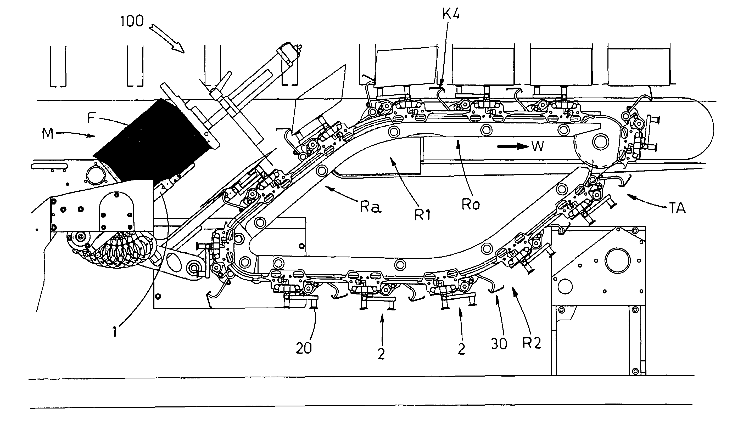
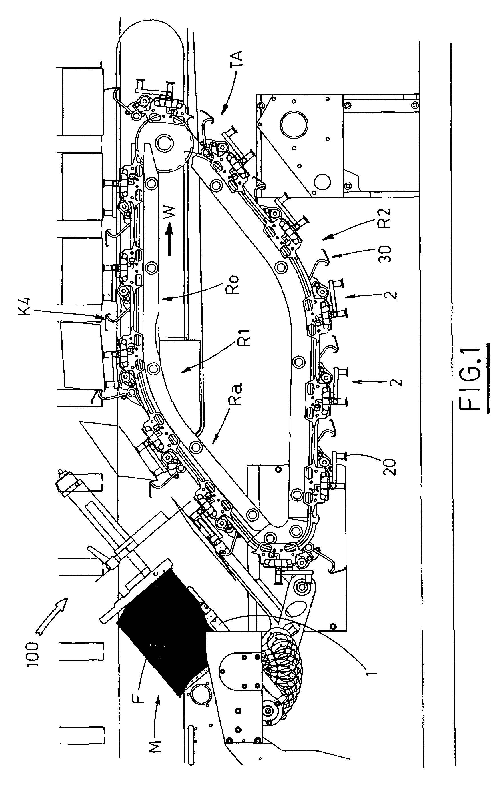
[0034]Having regards to the above Figures, reference numeral 100 indicates the proposed station, associated to a boxing machine, of substantially known type, which can be operated continuously or stepwise.

[0035]A magazine M, situated in the station 100, houses flat folded blanks F, piled up, aimed at being stripped away one by one from the pile bottom, by withdrawing means 1, e.g. a rocker arm, having suction cups set under vacuum condition.

[0036]An auxiliary conveying line TA is situated downstream of the withdrawing means 1 and extends along an endless loop path, which defines a work run R1 and a return run R2, along the operation direction W.

[0037]The work run R1 includes, in turn, an upward portion Ra, followed by a horizontal portion Ro (FIG. 1).

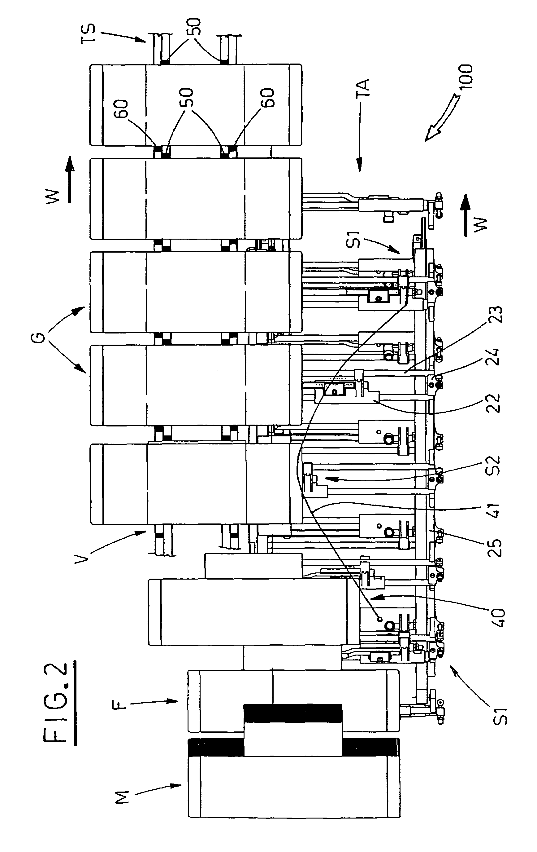
[0038]A box conveying line TS of the boxing machine begins beside the auxiliary conveying line TA and extends parallel thereto, in the feeding direction W of the latter. The box conveying line TS extends in a way that, in turn, it is pl...


PUM


Abstract

In a station of a boxing machine, for withdrawing and erecting flat folded tubular blanks into boxes, a blank withdrawing rocker arm strips out a flat folded blank from a magazine and places it onto a operating member situated below and associated to an auxiliary conveying line. The auxiliary conveying line extends along a close loop path. Gripping suction cups associated to the operating member engage the lower side of the blank. An erecting arm with a shaped flap makes edge-resting sides of the blank rotate synchronously, about respective articulation lines adjoining to a lower side, until a corresponding box is erected. A shaped guide engages with the carriage and moves the box laterally with respect to the auxiliary conveying line, to insert the box into a corresponding seat on a box conveying line situated beside the auxiliary conveying line.

Description

FIELD OF THE INVENTION[0001]The invention relates to the automatic machines for packaging articles, known as boxing machines.BACKGROUND OF THE INVENTION[0002]According to a widespread design, the boxing machines include a magazine, in which the tubular blanks are piled up, in flat folded configuration, and then withdrawn therefrom one by one, erected to define open boxes, and finally placed onto a box conveying line, which extends besides an article conveying line; the box conveying line and the article conveying line are moved in reciprocal step relation. The articles are introduced into the boxes by pushing means, moving longitudinally, synchronously with said conveying lines, and operated crosswise thereto; the boxes are then closed by suitable devices, situated downstream, along the box conveying line.[0003]Erecting flat folded tubular blanks into boxes, after their withdrawal from the magazine, is known in technical jargon as “rhombus-opening”, and includes the rotation of the ...

Claims


Application Information

Patent Timeline
Patent Type & Authority Patents(United States)
IPC IPC(8): B65B43/30B31B1/76B31B50/76B31B50/78
CPCB65B5/024B65B59/00B65B43/265B65B21/242B31B50/80B65B59/003
Inventor MONTI, GIUSEPPE
Owner MARCHESINI GROUP SPA
Why Eureka
Try Eureka