

Electric screwdriver
- Summary
- Abstract
- Description
- Claims
- Application Information
AI Technical Summary
Benefits of technology
Problems solved by technology
Method used
Image

Examples
first embodiment
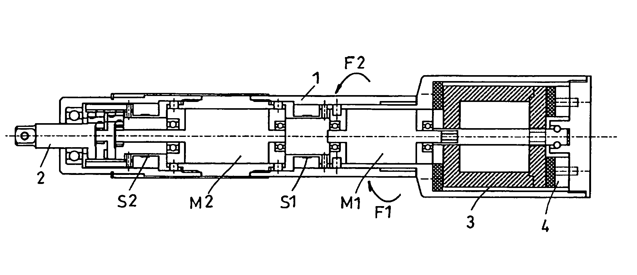
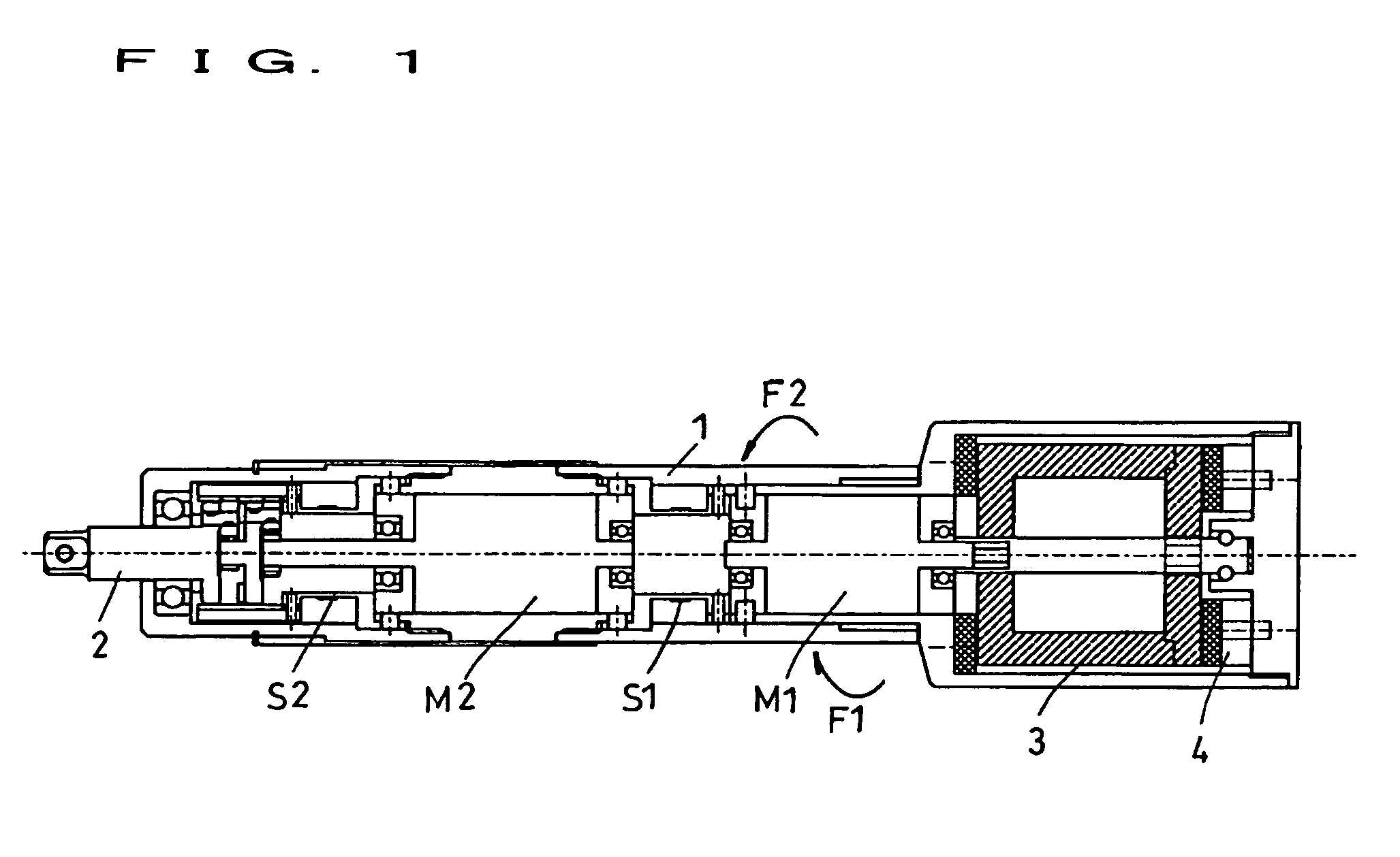
[0021]FIG. 1 to FIG. 3 indicate the electric screwdriver according to the present invention.
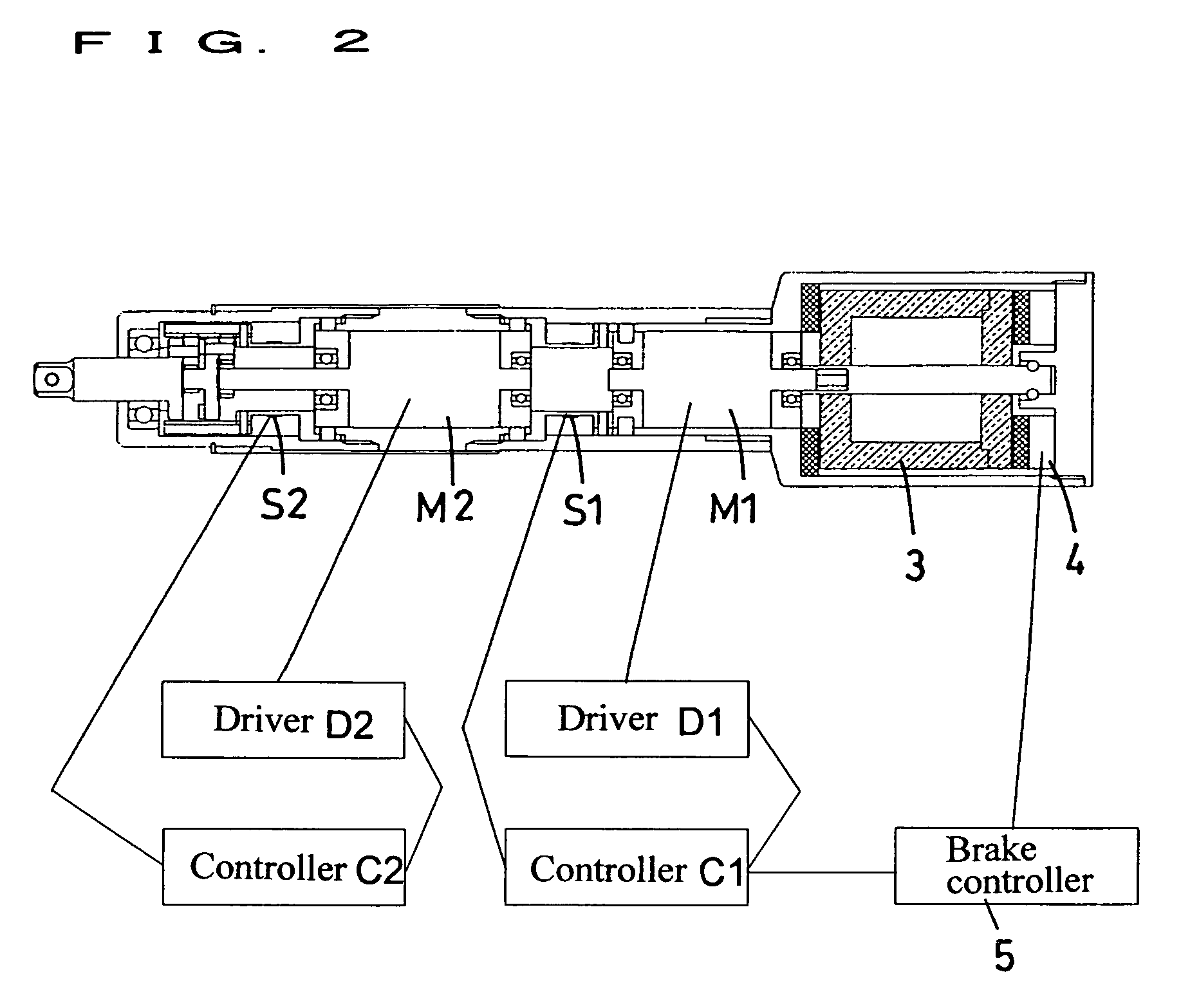
[0022]This electric screwdriver is a electric screwdriver designed to transmit the rotational driving force of a motor M2 to the bit (not illustrated) through a bit holder 2, characterized in that it comprises a flywheel 3 rotatively driven by a motor M1 other than said motor M2 in the direction same as the direction of rotation of the bit holder 2, a brake 4 generating a reactive force F1 in the direction offsetting the reactive force F2 transmitted from the bit to the body casing 1 through the bit holder 2, by braking this flywheel 3, and a brake operating mechanism 5 for operating the brake 4 in response to the magnitude of the reactive force F2 transmitted from the bit to the body casing 1 through the bit holder 2.
[0023]In this case, the motor M1 rotatively driving the flywheel 3 is driven and controlled by a controller C1 and a driver D1, in response to the output signal of a torque sens...
second embodiment
[0038]FIG. 4 to FIG. 6 indicate the electric screwdriver according to the present invention.
[0039]This electric screwdriver is an electric screwdriver designed to transmit the rotational driving force of a motor M to the bit (not illustrated) through a bit holder 2, characterized in that it comprises a flywheel 3 rotatively driven by a motor M common to said motor M in the direction same as the direction of rotation of the bit holder 2, a brake 4 generating a reactive force F1 in the direction offsetting the reactive force F2 transmitted from the bit to the body casing 1 through the bit holder 2, by braking this flywheel 3, and a brake operating mechanism 5 for operating the brake 4 in response to the magnitude of the reactive force F2 transmitted from the bit to the body casing 1 through the bit holder 2.
[0040]In this case, the motor M is driven and controlled by a controller C and a driver D, in response to the output signal of a torque sensor S disposed at a proper position of th...
PUM
 Abstract
Description
Claims
Application Information