Hospital bed having a drive wheel unit

a drive wheel unit and hospital bed technology, applied in the field of carriers, can solve the problems of manual movement of the carrier frame b>10/b>, inconvenience for the medical staff, and bringing uncomfortable feelings to the nearby people, and achieve the effect of reducing friction

Inactive Publication Date: 2007-12-25
LEE PAO LING
View PDF9 Cites 14 Cited by
  • Summary
  • Abstract
  • Description
  • Claims
  • Application Information

AI Technical Summary

Benefits of technology

[0005]The object of the present invention is to provide a powered carrier, such as a hospital bed having a drive wheel unit for mechanically moving the carrier frame when required, thereby eliminating the drawbacks encountered during use of the conventional hospital bed.
[0007]The aforesaid hospital bed further includes a lifting-and-lowering device. When it is desired to mechanically move the carrier frame, the drive wheel unit is lowered to the lower position by means of the lifting-and-lowering device, wherein the carrier frame is moved mechanically upon actuation of the motor. For manually moving the carrier frame, the drive wheel unit can be moved to the upper position by means of the lifting-and-lowering device so as to eliminate the friction generated due to engagement between the drive wheel unit and the ground surface when the former is at the lower position.

Problems solved by technology

One drawback of the aforesaid conventional hospital bed resides in that the carrier frame 10 needs to be moved manually.
Manually moving the carrier frame 10 is laborious, thereby causing inconvenience to the medical staff, who already has to burden overwork due to short stuff.
Since the walking path in the hospital is not very large due to limited area, the number of the medical staff moving the carrier frame 10 may block the walking path or cause traffic jam, thereby bringing uncomfortable feelings to the nearby persons who are happened to be around the carrier frame 10.

Method used


Image

  • Hospital bed having a drive wheel unit
  • Hospital bed having a drive wheel unit
  • Hospital bed having a drive wheel unit

Examples


Embodiment Construction

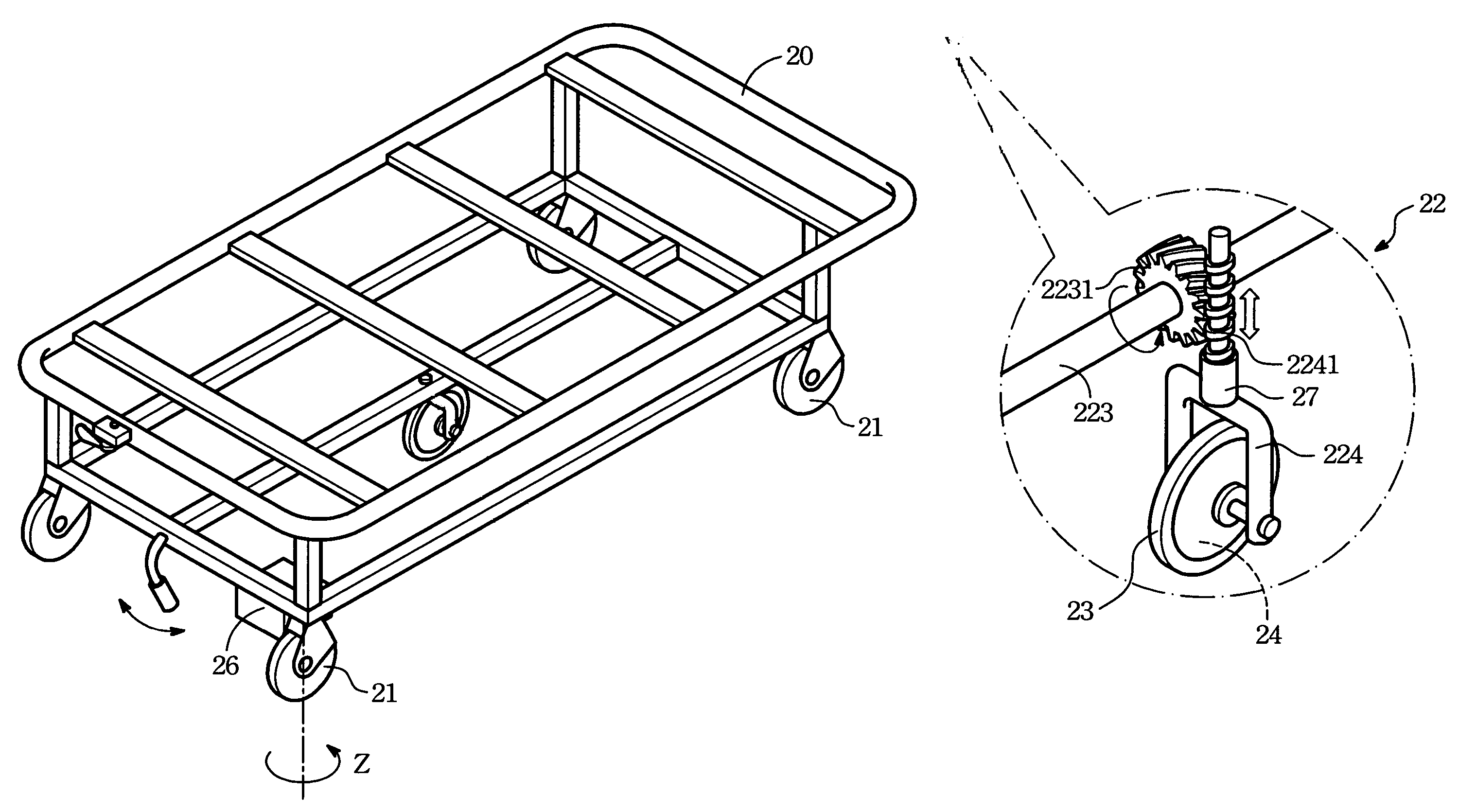
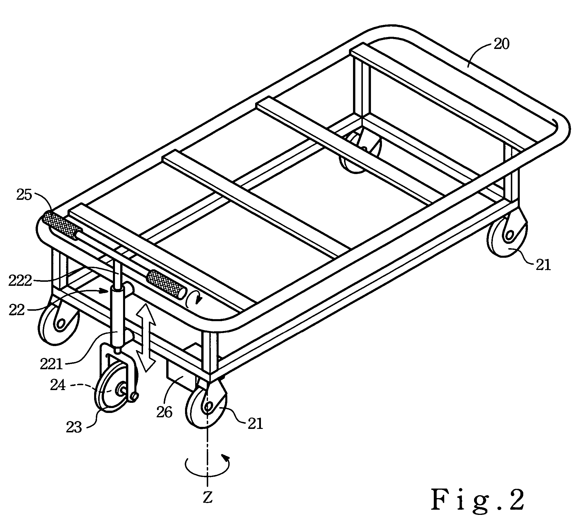
[0020]Referring to FIG. 2, a perspective view of the first embodiment of a hospital bed according to the present invention is used in the hospital for transporting patient from one place to the other. Alternately, the bed is used in the patient ward. The first embodiment includes a rectangular carrier frame 20, a driven wheel unit consisting of four casters 21, a lifting-and-lowering device 22, a drive wheel unit 23, a motor unit 24, a steering mechanism 25, and a power source 26 (generally a battery).

[0021]The carrier frame 20 is generally rectangular, and has a bottom portion. The casters 21 are mounted rotatably at four corners of the bottom portion in such a manner that the casters 21 are rotatable about the vertical axes Z so that the carrier frame 20 can be moved in a direction by virtue of manual operation.

[0022]The lifting-and-lowering device 22 includes a steering mechanism 25, a holding post 221, and a fork unit 222. The holding post 221 is secured to one end of the carrie...


PUM


Abstract

A hospital bed includes a carrier frame, a driven wheel unit disposed below the frame, a motor unit, a drive wheel unit disposed below the frame and coupled operably to the motor unit in such a manner that actuation of the motor unit results in rotation of the drive wheel unit. A lifting-and-lowering device interconnects the frame and the drive wheel unit for lowering and lifting the drive wheel unit with respect to the driven wheel unit between an upper position, in which, the drive wheel unit is disposed at an elevation above the driven wheel unit, and a lower position, in which lower surfaces of the driven and drive wheel units are flush with each other.

Description

FIELD OF THE INVENTION[0001]The present invention relates to a carrier, more particularly to a carrier, such as a hospital bed having a carrier frame and a drive-wheel unit for moving the carrier frame when desired.BACKGROUND OF THE INVENTION[0002]Due to rapid innovation of transportation technology, plenty of portable transport vehicles are used widely in order to transport things (especially heavy load) from one place to the other. For instance, a movable bed is an indispensable article in a hospital for transporting a patient (who is usually inconvenient to walk by itself) from one place to another, like taking the patient from the ward to an operation room or an X-ray room and vice versa.[0003]Referring to FIG. 1, a perspective view of a conventional hospital bed is shown to include a carrier frame 10, four casters 11 mounted rotatably to four corners of the carrier frame 10, and left and right safety rails 12 mounted at two opposite sides of the carrier frame 10. The safety rai...

Claims


Application Information

Patent Timeline
Patent Type & Authority Patents(United States)
IPC IPC(8): B62D51/04
CPCA61G7/08B62B2301/08
Inventor LEE, PAO-LING
Owner LEE PAO LING
Why Eureka
Try Eureka