
Method of forming reflecting dielectric mirrors

a dielectric mirror and mirror technology, applied in the optical field, can solve the problems of fragile mirror fabrication, high cost, and limited control over and achieve the effect of improving the optical properties of mirrors and reducing the cost of production

Inactive Publication Date: 2007-12-25
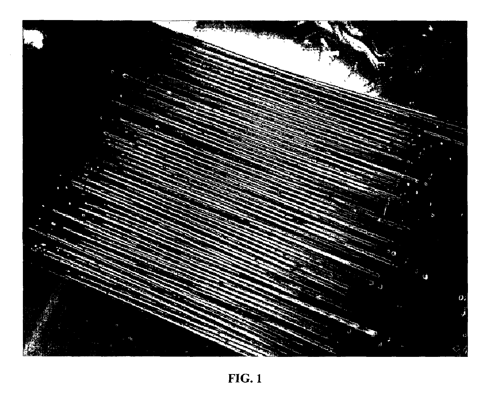
MASSACHUSETTS INST OF TECH
View PDF34 Cites 23 Cited by
  • Summary
  • Abstract
  • Description
  • Claims
  • Application Information

AI Technical Summary

Problems solved by technology

However, the control over their optical properties has so far remained relatively limited.
Conversely, dielectric mirrors are used to precisely control and manipulate light in high performance optical applications, but fabrication of these fragile mirrors has been mostly restricted to planar geometries and remains costly.
The degree of utilization of all types of dielectric mirrors has been impeded by cost and complexity associated with their fabrication, which typically involves physical or chemical vapor deposition of many alternating layers in sequence, and by difficulties associated with depositing these mirrors on non-planar surfaces.
In addition, the mirror films are typically fragile and not freestanding.

Method used


Image

  • Method of forming reflecting dielectric mirrors
  • Method of forming reflecting dielectric mirrors
  • Method of forming reflecting dielectric mirrors

Examples


Embodiment Construction

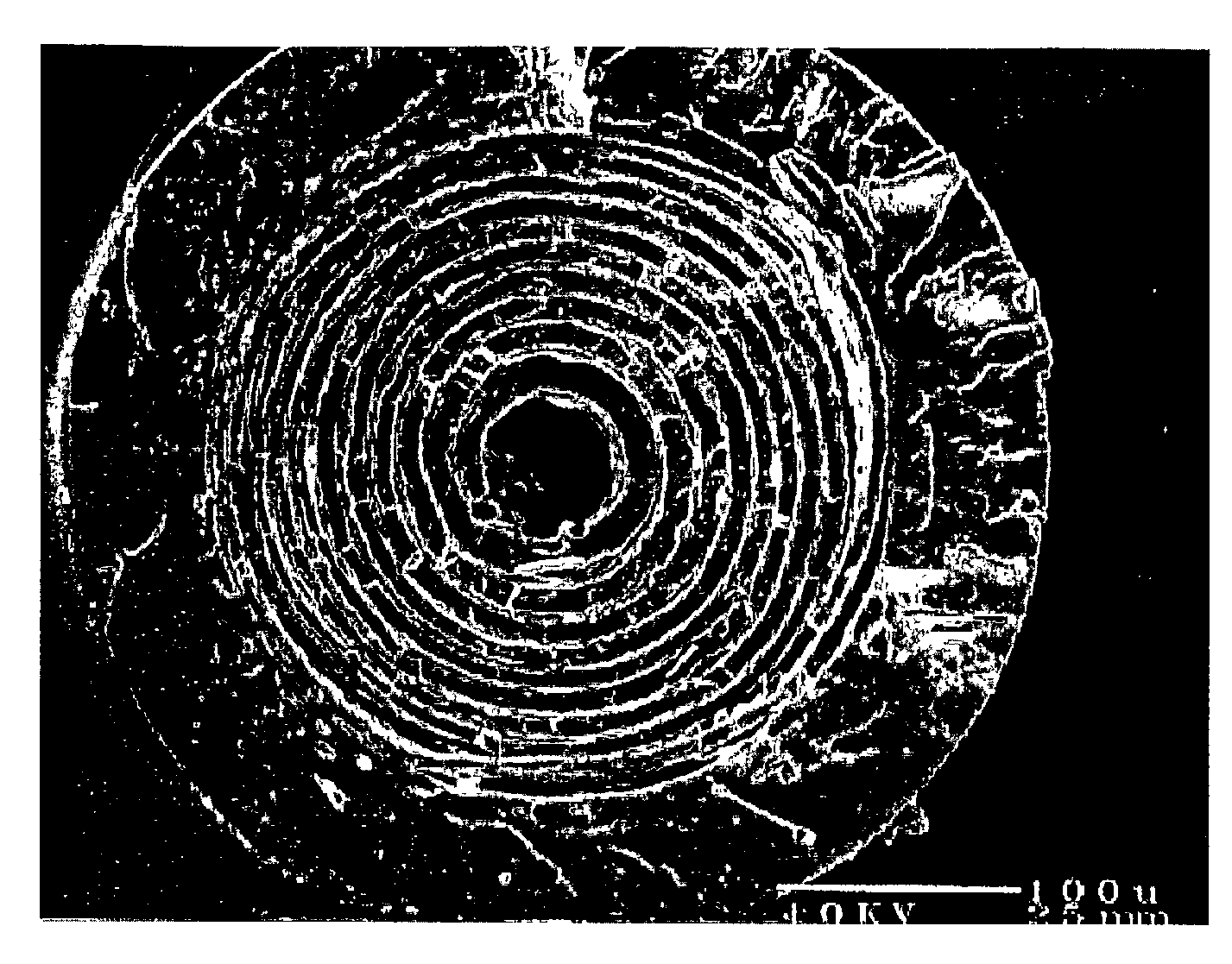
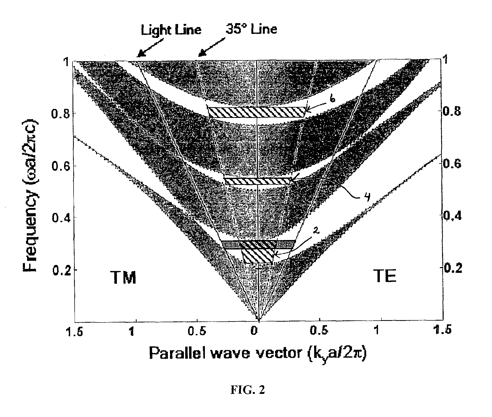
[0018]The invention combines some of the advantages of two dissimilar materials in the fabrication of polymeric fibers having on or within them a multilayer dielectric mirror structure. Thermal processing techniques are used to create and then reduce a macroscopic layered dielectric structure to sub-micron length scales, thus establishing a photonic band gap in the mid-IR range. The selection of materials involves the empirical identification of a pair of amorphous materials, such as poly(ether-sulfone)(PES) and arsenic triselenide (As2Se3), which have substantially different refractive indices yet have similar thermo-mechanical properties within a certain thermal processing window. Amorphous materials, such as inorganic glasses and some thermoplastic polymers, have gradual variation in viscosity with temperature when compared to crystalline materials. This is due to the lack of a first-order-thermodynamic transition in an amorphous material as it is cooled from a melt to the glassy...


PUM

PropertyMeasurementUnit
sizeaaaaaaaaaa
sizeaaaaaaaaaa
diameteraaaaaaaaaa

Abstract

A mirror structure includes a plurality of features of a defined size. The features include alternating spatial units of a chalcogenide glass and a thermoplastic polymer, and are specifically arranged in an ordered form so that the structure is highly reflective. Thermally-assisted methods are introduced for forming such structures.

Description

PRIORITY INFORMATION[0001]This application claims priority from provisional application Ser. No. 60 / 305,839 filed Jul. 16, 2001 and provisional application Ser. No. 60 / 351,066 filed Jan. 23, 2002.[0002]This invention was made with government support under Grant No. DAAD19-01-1-0647 awarded by the Army Research Office and Grant Number ECS-0123460 awarded by the NSF. The government has certain rights in the invention.BACKGROUND OF THE INVENTION[0003]The invention relates to the field of optics, and in particular to the creation of reflecting dielectric mirror structures, such as fibers.[0004]Polymer fibers have become ubiquitous in applications such as textile fabrics, due to their excellent mechanical properties and availability of low-cost, high-volume processing techniques. However, the control over their optical properties has so far remained relatively limited. Conversely, dielectric mirrors are used to precisely control and manipulate light in high performance optical applicatio...

Claims


Application Information

Patent Timeline
Patent Type & Authority Patents(United States)
IPC IPC(8): B32B3/26G02B5/28G02B1/10G02B5/08G02B6/00G02B6/02
CPCG02B5/0825G02B6/02304G02B5/0841Y10T428/24975Y10T428/31645Y10T428/249924Y10T428/31649Y10T428/31616
Inventor FINK, YOELHART, SHANDONMASKALY, GARRYTEMELKURAN, BURAK
Owner MASSACHUSETTS INST OF TECH
Learn More