AI technical title is built by Patsnap AI team. It summarizes the technical point description of the patent document.
a technology of motion compensation and light-emitting apparatus, which is applied in the direction of lighting and heating apparatus, instruments, optical radiation measurement, etc., can solve the problems of inferior performance, unsteady column of light, and conventional light-emitting devices
Active Publication Date: 2007-12-25
FEINSOD MATTHEW +1
View PDF12 Cites 9 Cited by
Summary
Abstract
Description
Claims
Application Information
AI Technical Summary
This helps you quickly interpret patents by identifying the three key elements:
Problems solved by technology
Method used
Benefits of technology
Benefits of technology
[0005]The present apparatus may be lightweight, portable, compact, inexpensive to manufacture and easy to assemble.
[0006]In one embodiment of the present invention, a motion-compensating light-emitting device is provided which utilizes two miniature gyroscopes (for example, microelectromechanical system (“MEMS”) such as model ADXRS150 manufactured by Analog Devices, Inc.) arranged to measure vertical and horizontal angular movements (i.e., pitch and yaw) of the device. These gyros may have a relatively small volume (such as less than 0.15 cm3), low weight (such as less than 500 mg), and small size (such as 7 mm×7 mm×3 mm or less).
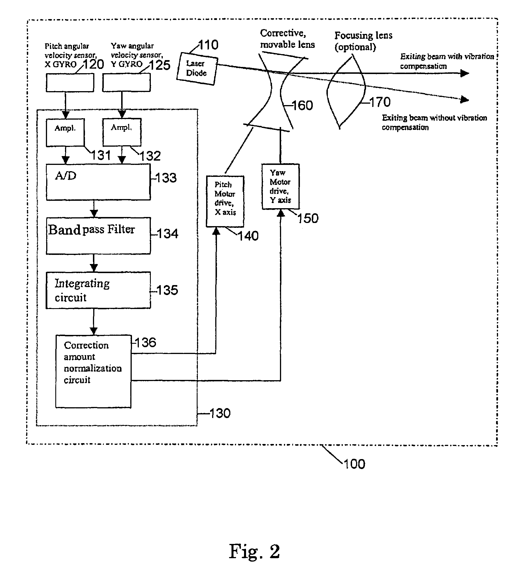
[0008]In the present invention, the sensing device(s) (such as the two gyros or accelerometers) may be arranged so as to interact with an optical apparatus to cause the exiting light rays to be refracted in a compensating or opposite direction to a measured undesired angular movement or motion. For instance, if one of the gyros measures a downward tilt or undesired angular movement of the light-emitting device, then the light rays may be refracted in a proportional amount in the upward direction so as to cancel the effects of the undesired angular movement or vibration. As is to be appreciated, a similar result may also be obtained for undesired angular movements or motions in the left and / or right direction.
Problems solved by technology
However, conventional light-emitting devices may be affected by unintentional angular movements (e.g., fine vibrations from the machine in which a laser is encased, fine tremors from a shaking hand holding a laser, etc.) and, as a result, generate an unsteady column of light—producing an effect that may cause inferior performance.
These unwanted vibrations are often amplified when the person maneuvering the device is nervous.
Thus, only the angular changes (particularly those in the 1 to 5 Hz frequency region, typical for a hand tremor) cause the undesirable movements of the projected light on the target.
Method used
Image
Click on the blue label to locate the original text in one second.
Reading with bidirectional positioning of images and text.
Examples
Embodiment Construction
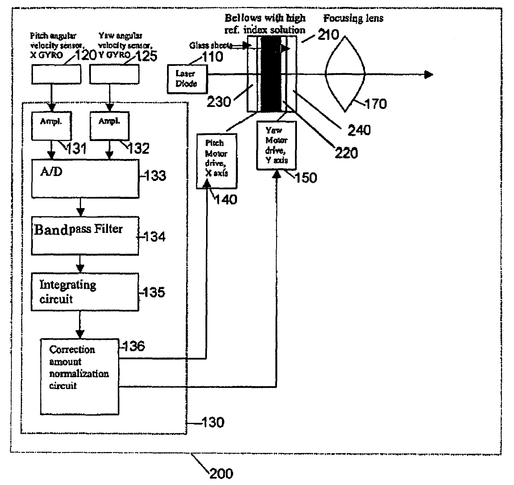
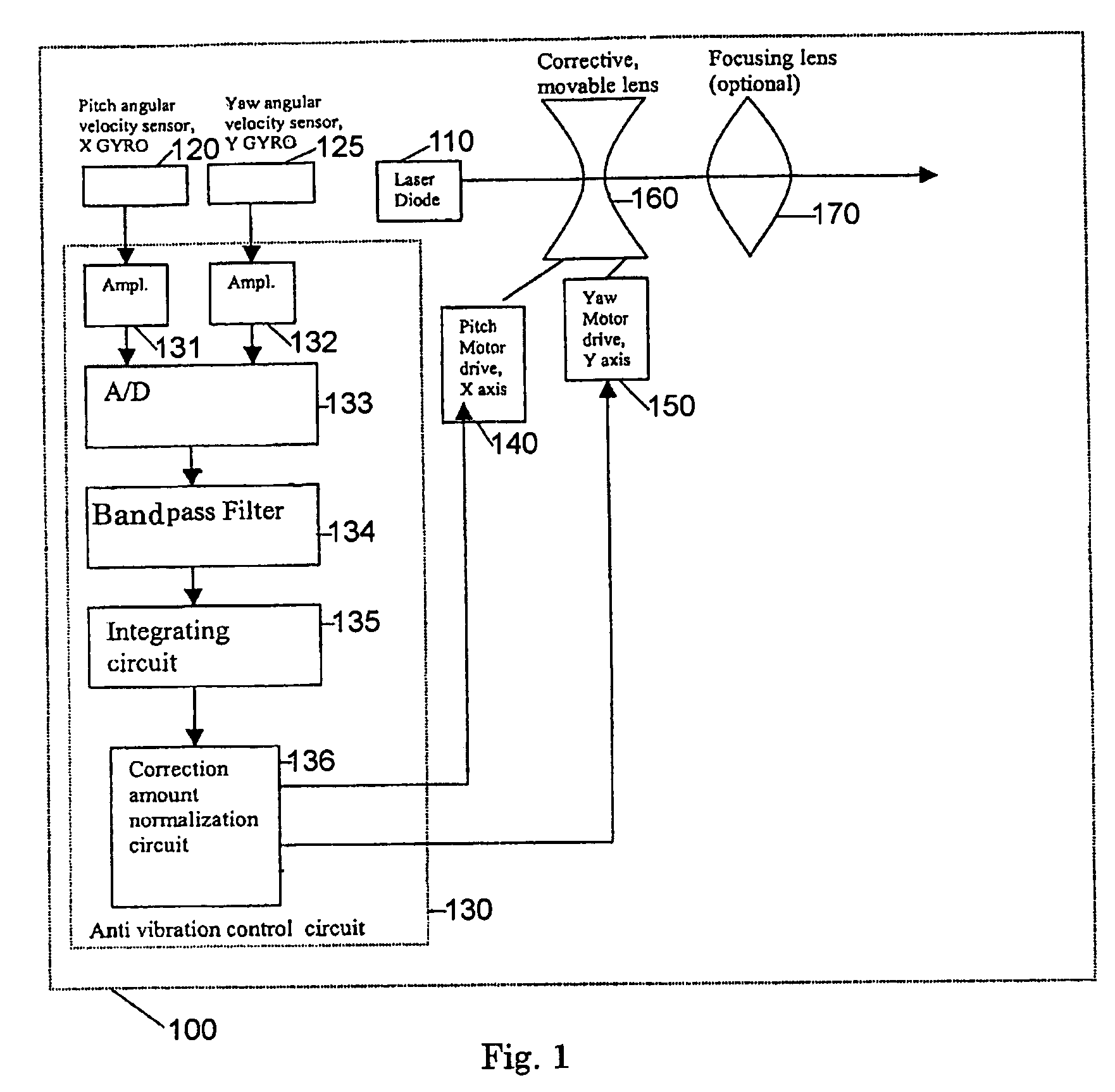
[0018]FIG. 1 is a diagram of a laser diode pointer 100 which includes vibration or motion compensation circuitry in accordance with an embodiment of the invention. A visible laser diode 110 may be used as the light source. There are several ways of implementing the vibration compensation scheme. In accordance with an embodiment of the invention, two angular velocity sensors (gyros) 120 and 125 are aligned in orthogonal directions and used to measure the angular movements in the pitch and yaw axis (also referred to as the X and Y axis). The output of gyros 120 and 125 are amplified by two amplifiers 131 and 132 respectively and / or sampled by an A / D converter 133 in anti-vibration control circuit 130. The sampled signal may be passed to a band frequency filter 134 where the portion of the signal associated with the rapid, unwanted angular motions of the pointer in this example, typically that portion between 1 and 5 Hz, is extracted. Although a band frequency filter having a range of ...
PUM
Abstract
A light-emitting apparatus, for enabling a spot of light to be projected on a desired target located a distance away such that the spot is projectable on the desired target without any or substantially any undesired movement. The apparatus may include a housing, a light generating device located within the housing and operable to generate a beam of light, a sensing device or devices for sensing an undesired action of the housing, a control circuit operable to provide a control signal corresponding to the sensed undesired action, and a drive device operable to counter act all or at least some of the undesired action of said housing in accordance with said control signal. The sensing device or devices may be one or more gyroscopes, accelerometers or other such devices.
Description
BACKGROUND OF THE INVENTION[0001]The present invention relates to light-emitting devices and particularly to those devices intended to produce a beam in a selected direction such as toward a target of interest. The invention provides motion-compensation technology suitable for use with such light-emitting devices, which may dampen and / or substantially eliminate the effect of unintentional motion, vibration, or movements, such as angular movements, caused by mechanical vibrations, hand tremors, and so forth.[0002]Light-emitting devices, such as laser diode devices, are used in a variety of consumer, computer, business, medical, scientific, military, outdoor, telecommunication and industrial products, including but not limited to compact disk (CD) players and computer CD-ROM drives, digital video disk (DVD) players and DVD-ROM drives, laser printers, laser pointers, barcode scanners, measurement devices, rangefinders, scopes, industrial material processing devices, marking and cutting...
Claims
Application Information
Patent Timeline
Application Date:The date an application was filed.
Publication Date:The date a patent or application was officially published.
First Publication Date:The earliest publication date of a patent with the same application number.
Issue Date:Publication date of the patent grant document.
PCT Entry Date:The Entry date of PCT National Phase.
Estimated Expiry Date:The statutory expiry date of a patent right according to the Patent Law, and it is the longest term of protection that the patent right can achieve without the termination of the patent right due to other reasons(Term extension factor has been taken into account ).
Invalid Date:Actual expiry date is based on effective date or publication date of legal transaction data of invalid patent.

