Device and method for non-invasive optical measurements

a non-invasive, optical measurement technology, applied in the direction of medical science, sensors, diagnostics using pressure, etc., can solve the problems of large variability of individual parameters affecting the signal of concrete patients, the way of expanding non-invasive techniques, and significant difficulties, so as to maximize the homogeneity of the first and increase the amount of light

Active Publication Date: 2007-12-25
ORSENSE LTD
View PDF29 Cites 217 Cited by
  • Summary
  • Abstract
  • Description
  • Claims
  • Application Information

AI Technical Summary

Benefits of technology

[0007]There is a need in the art to facilitate non-invasive optical measurements of blood parameters by providing a novel device and method capable of stabilizing the optical response of an illuminated region in a patient's body.
[0009]The present invention utilizes redirecting reflections of light on its way towards the region of interest (i.e., blood vessel) back to the region of interest. This is implemented using a diffuser accommodated in the optical path of light reflected from the body portion under measurements. Due to the provision of a diffuser, illuminating light that is reflected from the skin and bones is “collected” and directed back to the region of interest. The use of a diffuser stabilizes both the reflected and transmitted responses of the illuminated region, and causes a stable increase of the reflected signal.
[0013]a light directing assembly comprising a light diffuser for scattering back light incident thereto, to thereby direct the illuminating light or the light coming from the body portion back towards the body portion, thereby increasing amount of light reaching a region of interest inside the body portion and thus maximizing homogeneity of the first and second detected light signals.
[0016]The device may be configured for operating in the occlusion-release mode. To this end, the device includes a pressurizing assembly operable for applying an over-systolic pressure to the patient's body so as to create a condition of artificial blood kinetics in the region of interest and maintain this condition for a certain time period. The pressurizing assembly may be configured and operable for applying a secondary controllably varying under- or over-systolic pressure to the body within the region of interest, so as to alter said condition of artificial blood kinetics over a predetermined time interval within said certain time period, to thereby modulate the amount of blood under measurements.
[0021]generating second measured data indicative of the detected reflected light; the method providing for increasing amount of light reaching the region of interest inside the body portion, and for maximizing homogeneity of the first and second detected light signals.

Problems solved by technology

The two main challenges, that any non-invasive optical method has to deal with, are as follows: (1) the low signal-to-noise ratio, and, (2) the large variability of individual parameters influencing the signal of concrete patients.
It is known that for blood parameters other than oxygen saturation, e.g., glucose concentration, significant difficulties have been encountered, because their absorption spectral behavior in red and near infrared regions is not as remarkable as for the oxygenized hemoglobin.
Hence, the main limitations on the way of expanding the non-invasive techniques to the measurements different from pulse oximetry are associated with the limited selectivity of the absorption based method.

Method used


Image

  • Device and method for non-invasive optical measurements
  • Device and method for non-invasive optical measurements
  • Device and method for non-invasive optical measurements

Examples


Embodiment Construction

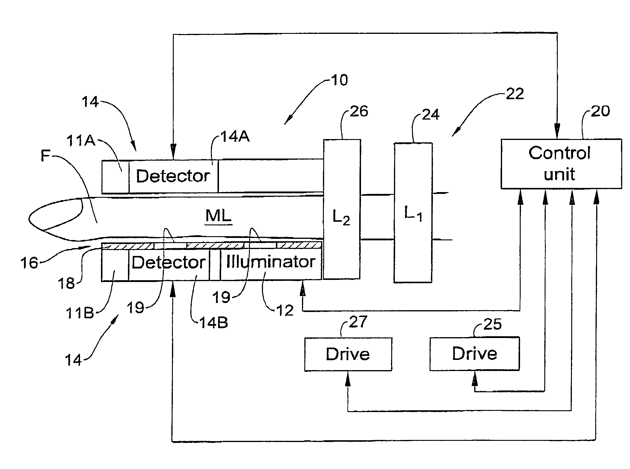
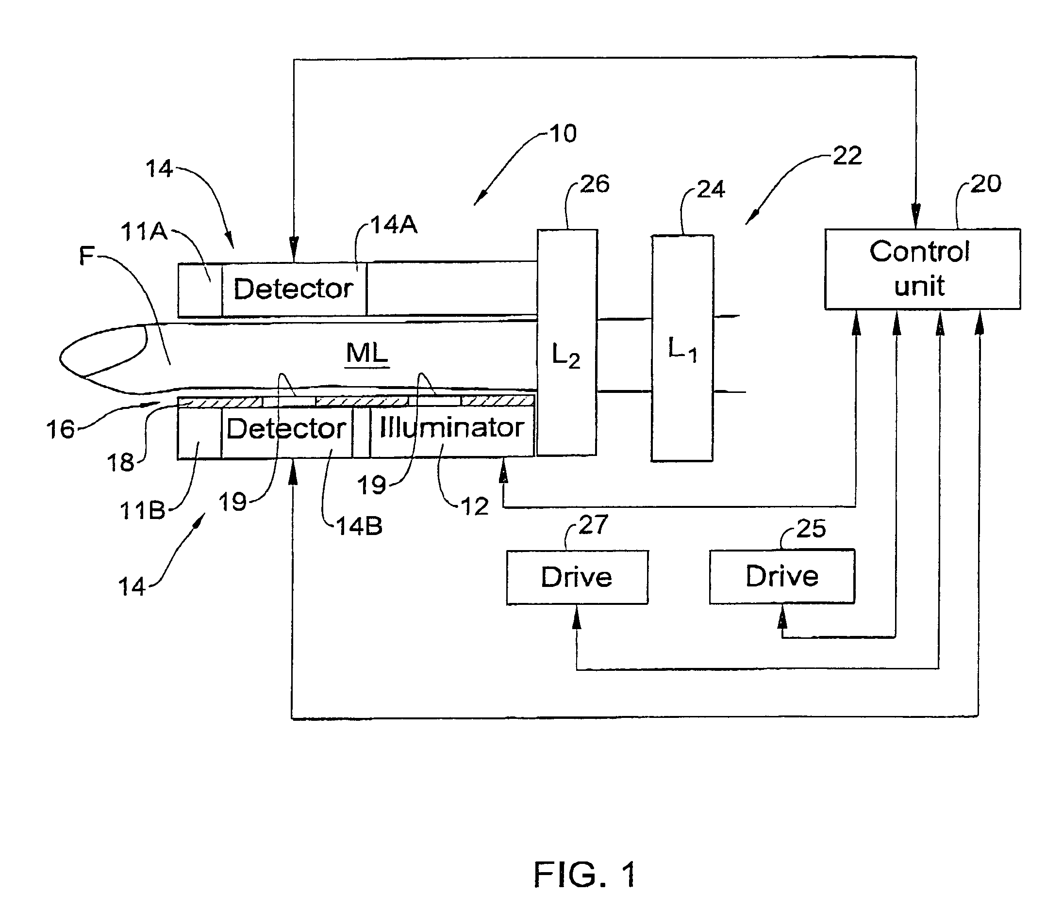
[0027]Referring to FIG. 1, there is schematically illustrated an optical measurement device 10 of the present invention for use in non-invasive measurements on a patient's body, e.g., patient's finger F. The device 10 includes an illumination assembly 12; a detection assembly 14; and a light directing assembly 16. A control unit 20 is provided for operating the illumination and detection assemblies and for receiving and processing measured data coming from the detection assembly.

[0028]The illumination assembly 12 is accommodated so as to direct illuminating light towards the finger F. The illumination assembly 12 may utilize one or more light emitting elements, e.g., LED(s). Preferably, a matrix of LEDs is used. In this specific example of measuring blood parameters, the illumination assembly 12 is designed for generating light of different wavelengths (at least two different wavelengths), which can be implemented by using different light emitting elements or a single broadband illu...


PUM


Abstract

An optical measurement device and method are presented for use in non-invasive measurements on a patient's body. The device comprises an illumination assembly configured and operable to generate illuminating light of a predetermined wavelength range; a detection assembly; and a light directing assembly. The detection assembly comprises a first detector unit for detecting a first light signal transmitted through an illuminated body portion and generating first measured data indicative of the detected transmitted light, and a second detector unit for detecting a second light signal reflected from the illuminated body portion and generating second measured data indicative of the detected reflected light. The light directing assembly comprises a light diffuser for scattering back light incident thereto, to thereby direct the illuminating light or the light coming from the body portion back towards the body portion. This technique provides for increasing the amount of light reaching a region of interest inside the body portion and maximizing homogeneity of the first and second detected light signals.

Description

FIELD OF THE INVENTION[0001]This invention relates to a device and method for non-invasive optical measurements on a human body, which is particularly useful for measuring blood-related parameters.BACKGROUND OF THE INVENTION[0002]Non-invasive (in vivo) methods for measuring various blood-related parameters have become very popular due to the fact that these measurements, in distinction to invasive ones, do not involve the physical withdrawal of a blood sample from the patient's body. Optical monitoring techniques of the kind specified utilize the detection of light transmitted or reflected from the location on the patient's body under measurement, and are based on spectrophotometric measurements enabling the indication of the presence of various blood constituents based on known spectral behaviors of these constituents. These methods being applied in real medicine rather than in analytical chemistry create the basis for non-invasive blood tests, which present, no doubt, one of today...

Claims


Application Information

Patent Timeline
Patent Type & Authority Patents(United States)
IPC IPC(8): A61B5/00
CPCA61B5/0048A61B5/6838A61B5/14552A61B5/6826A61B5/1455A61B5/14532A61B5/0053
Inventor FINAROV, ALEXANDERFINE, ILYA
Owner ORSENSE LTD
Why Eureka
Try Eureka