

Folding belt filter
a belt filter and belt edge technology, applied in the direction of moving filter element filter, filtration separation, separation process, etc., can solve the problems of belt edge sludge overflow, add to process complexity and therefore cost, and overall cost of belt filter
Inactive Publication Date: 2008-01-01
LASERRAVE
View PDF58 Cites 14 Cited by
- Summary
- Abstract
- Description
- Claims
- Application Information
AI Technical Summary
Benefits of technology
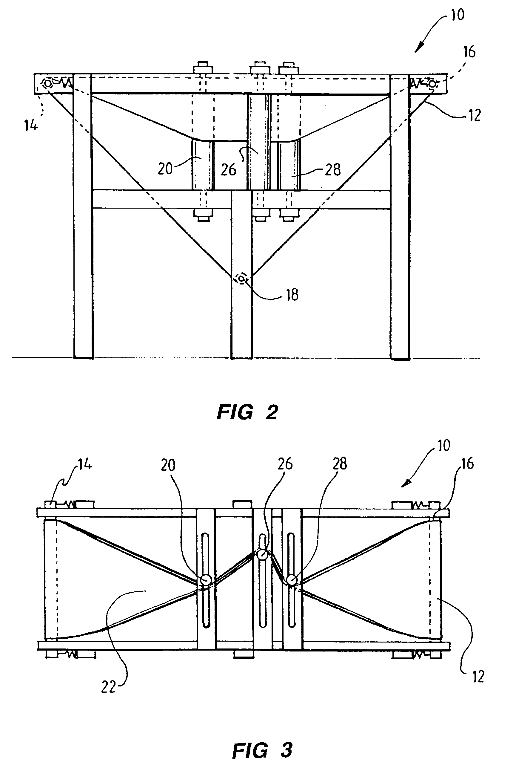
[0015]Further, the slurry level can be kept high within the cavity so that the full width of the compressing surfaces can be used for compression. Further, the level of slurry within the cavity can be easily monitored so that there can be an automatic feed of slurry into the cavity in response to changes in the level of slurry detected. However in another case the level is established and maintained by simply limiting the amount of the material being fed into the supporting shape.
[0017]This assists to ensure that the belt or belts where there are more than one does or do not greatly deform out of shape under any weight of slurry, as well as to assist in the tracking of the belt or belts.
[0020]In preference, the belt is formed and of a material so as to allow for repeated folding lengthwise along a central fold alignment. In this way, belt wear and tear can be reduced. Such a form and material can be such as to have the medial part somewhat more pliable than a remainder of the belt.
[0025]Furthermore, the rollers may preferentially be of a slotted or perforates type allowing for exudate to also pass through the side of a folded belt against the roller when being nipped. This construction also can assist in self-cleaning of the rollers.
[0026]In preference said rollers are slidably adjustable so as to enable said belt to be adjusted in its tensioning around said belt filter. This may also assist in the tracking of the belt.
Problems solved by technology
One problem with existing belt filters is that when a liquid sludge of low viscosity is fed onto the lower belt which provides an uppermost receiving surface which is substantially horizontal, the sludge may overflow an edge of the belt.
Obviously this all adds to the complexity and therefore cost of the process, as well as the overall cost of such belt filters.
Method used
View moreImage
Smart ImageViewing Examples

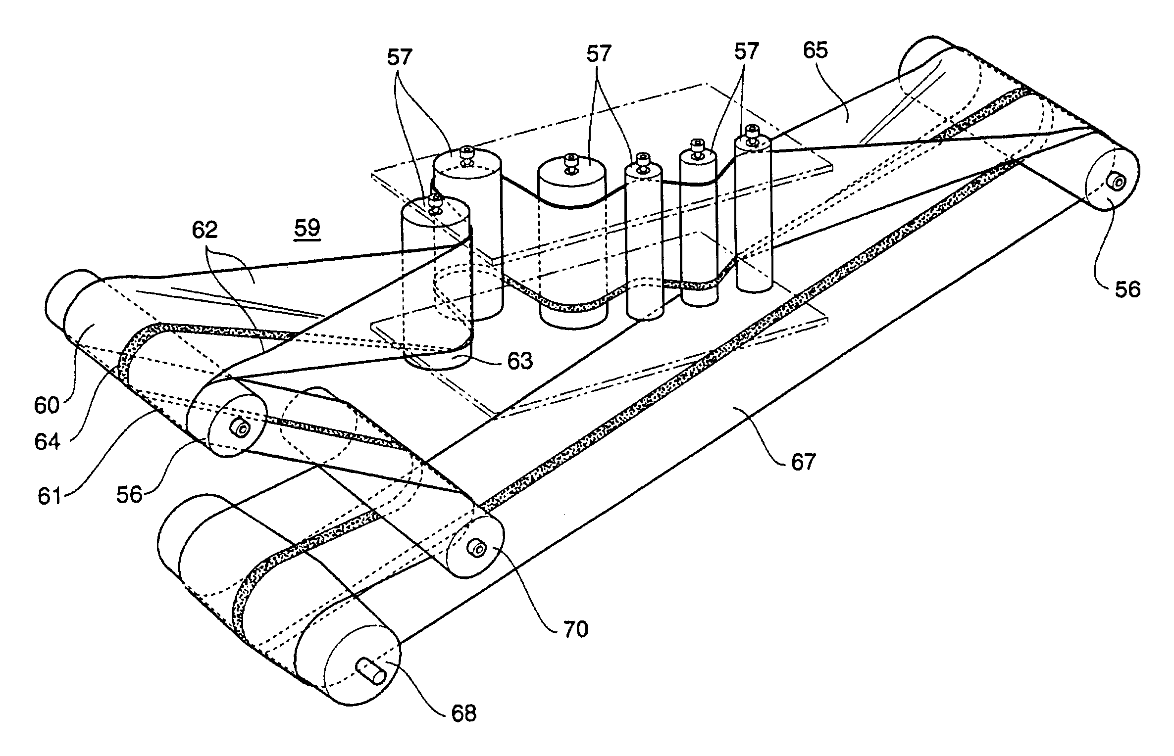
Examples
first embodiment
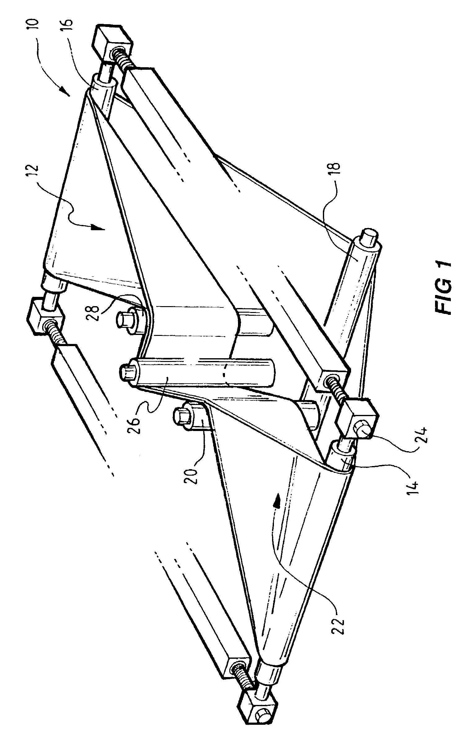
[0033]FIG. 1 is a perspective view of the invention;
[0034]FIG. 2 is a side cross sectional view of the first embodiment as shown in FIG. 1;
[0035]FIG. 3 is a top view of the first embodiment as shown in FIG. 1;
[0036]FIG. 4 is an exploded perspective view of the first embodiment as shown in FIG. 1;
[0037]FIG. 5 is a partial perspective view showing the folding of the belt;
[0038]FIG. 6 is a partial perspective view showing the reinforcing of the belt;
second embodiment
[0039]FIG. 7 is the invention;
third embodiment
[0040]FIG. 8 is a partial perspective view of a belt;
Login to View More PUM
| Property | Measurement | Unit |
|---|---|---|
| Shape | aaaaa | aaaaa |
Abstract
A belt filter for effecting separation of liquid from solids where, at the collection zone, a filter belt or belts is changed shape so as to provide a supporting shape to bold liquid, which is then fed into a nipping zone. In an embodiment there is a single belt used which is folded in a middle portion to provide the supporting shape.
Description
[0001]The present invention relates to a belt filter system for separation of material into liquid and solid components, a belt adapted for this purpose and a method for effecting some separation of solid and liquid components, and a method to assisting drying of sludge or slurry like materials.BACKGROUND ART[0002]Many industrial and commercial processes require the separation of a sludge or slurry into its component liquid and solid. This may be used to treat a sludge or slurry so as to remove a percentage of its liquid, or to produce a liquid with less solid particulate, or both. Some examples of such sludge or slurry to be so treated include sewage, industrial waste, paper pulp or mixtures, whether they be biological, chemical or mineral-based products.[0003]A belt filter system is known which uses two endless belts where one is located fully above the other and each belt is driven so that they will jointly come together downstream from a loading station whereby to capture and co...
Claims
Login to View More Application Information
Patent Timeline
 IPC IPC(8): B01D33/052B01D33/056B01D33/64B30B9/20B30B9/24
CPCB01D33/042B30B9/24B30B9/245B01D33/056
InventorDAY, PAUL HEDLEY
OwnerLASERRAVE