
Sampling frequency conversion device and sampling frequency conversion method

a frequency conversion and sampling frequency technology, applied in the direction of digital transmission, digital storage, instruments, etc., can solve the problems of inability of the frequency conversion method to convert the sampling frequency and be applied

Inactive Publication Date: 2008-01-01
KK TOSHIBA
View PDF5 Cites 0 Cited by
  • Summary
  • Abstract
  • Description
  • Claims
  • Application Information

AI Technical Summary

Benefits of technology

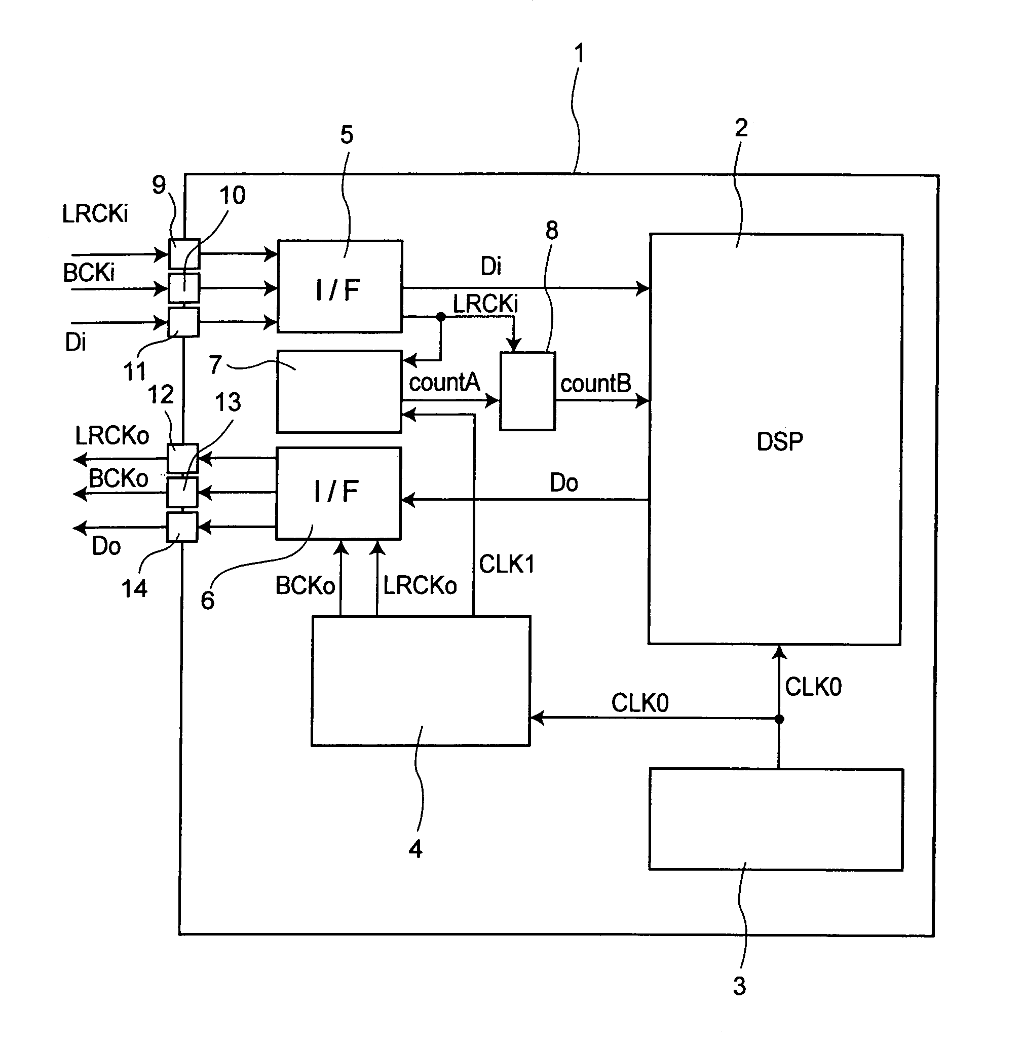
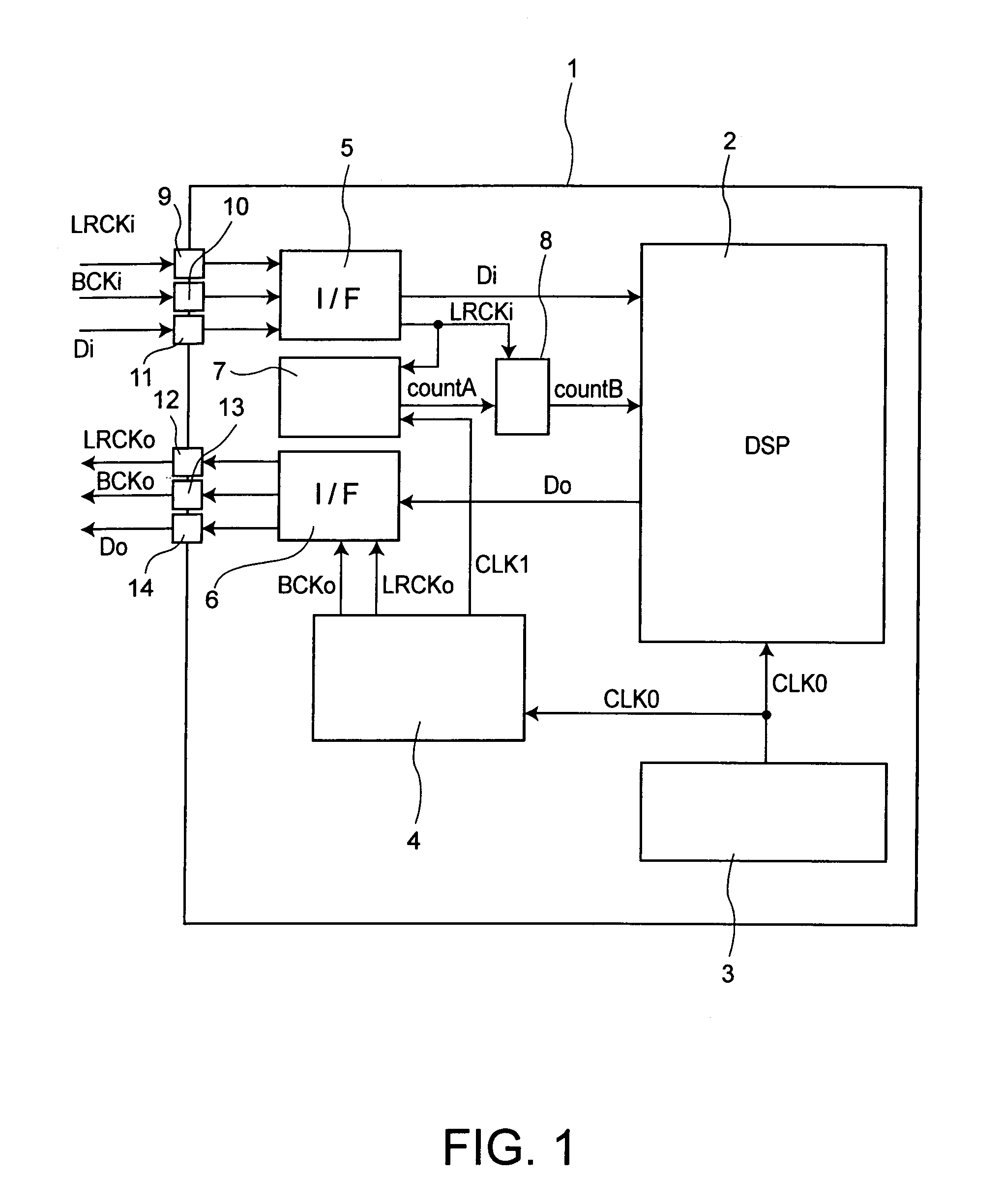
The present invention relates to a sampling frequency conversion device and method that can adjust the frequency of input data to output data with a different frequency. The device includes an internal circuit for processing data based on an input word clock and outputting the data, a clock generation circuit for generating an output word clock and a counter clock, a counter for counting the counter clock, and a register for holding the counter value in synchronization with the input word clock. The method includes executing a signal processing of input data based on an input word clock, generating an output word clock and a counter clock, and counting the counter clock. The device and method can adjust the sampling frequency of input data to output data with a different frequency.

Problems solved by technology

However, if a sampling frequency ratio of the input data and the output data is not previously known, the above described sampling frequency conversion method is incapable of converting the sampling frequency and of being applied.

Method used


Image

  • Sampling frequency conversion device and sampling frequency conversion method
  • Sampling frequency conversion device and sampling frequency conversion method
  • Sampling frequency conversion device and sampling frequency conversion method

Examples


first embodiment

[0026]When it is tried to execute all of detections of a phase shift amount and all of data correction processings only by a processor by means of firmware in an I / O system, and when it is tried to execute them every one sample, the processor has to execute many processings within limited time. In this case, if the processor cannot execute all processings within certain time, programs may be damaged.

[0027]For the above described circumstance, to operate the processor stably, it is required to reduce a burden on the processor by detecting a phase shift amount effectively and executing a correction processing for data.

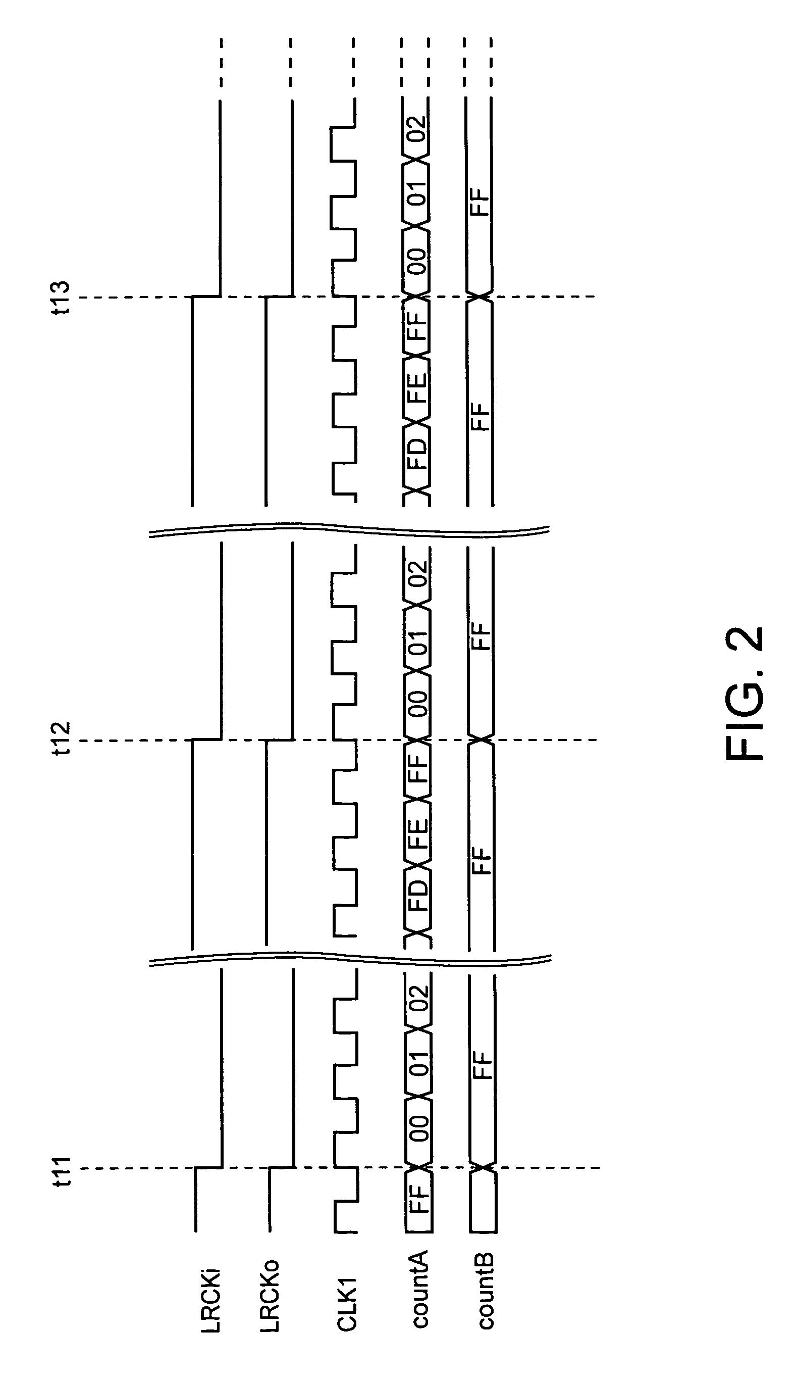
[0028]A sampling frequency conversion device according to a first embodiment of the present invention will be described with reference to FIGS. 1 to 6 below. Herein, a case where the sampling frequency conversion device according to this embodiment converts input data Di of a sampling frequency fs 1 to output data Do of a sampling frequency fs 2 is shown. A DSP (Digital ...

second embodiment

[0069]The sampling frequency conversion device according to a second embodiment of the present invention will be described with reference to FIGS. 7 to 14.

[0070]A configuration of the sampling frequency conversion device according to this embodiment will be described with reference to FIG. 7. FIG. 7 is a block diagram showing the configuration of the sampling frequency conversion device according to this embodiment. It is noted that the same constituent components as those described by use of FIG. 1 in the first embodiment are denoted by the same reference numerals, and descriptions for them are omitted.

[0071]A counter 15 (a first counter) is a 10-bit counter, and counts up in synchronization with a counter clock CLK1. An input word clock LRCKi is inputted from an I / F circuit 5 to the counter 15, and higher-order 2 bits of a counter value countA of counter 15 are shifted to a lower-order by one bit in synchronization with a drop of the input word clock LRCKi. Specifically, the count...


PUM


Abstract

A sampling frequency conversion device comprises an internal circuit for executing in synchronization with an internal clock a signal processing of input data fetched in accordance with an input word clock, and for outputting the input data having undergone the signal processing as output data, a clock generation circuit for generating from the internal clock an output word clock and a counter clock having a frequency which is equal to that of the output word clock multiplied by n (n: integer equal to two or more), a counter for counting the counter clock, and a register for holding a counter value of the counter in synchronization with the input word clock, and for outputting the held counter value to the internal circuit.

Description

CROSS-REFERENCE TO RELATED APPLICATIONS[0001]This application is based upon and claims the benefit of priority from the prior Japanese Patent Application No. 2003-163658, filed Jun. 9, 2003, the entire contents of which are incorporated herein by reference.FIELD OF THE INVENTION[0002]The present invention relates to a sampling frequency conversion device for converting a sampling frequency when sampling frequencies on input and output sides are different, and a sampling frequency conversion method of converting the same.BACKGROUND OF THE INVENTION[0003]When instruments using different frequencies are coupled to each other, it is necessary to convert a sampling frequency of the instrument on a sending side to that of the instrument on a receiving side.[0004]As one of representative techniques on the sampling frequency conversion method, there has been a method in which output data is constructed by over-sampling input data by N times and by thinning out the over-sampled data by 1 / M t...

Claims


Application Information

Patent Timeline
Patent Type & Authority Patents(United States)
IPC IPC(8): H04L7/00H04B14/04G11C7/00H03H17/06
CPCH03H17/0628
Inventor TANAKA, YOSHIYUKIOJIMA, YOSHINARIWAKASUGI, JUN
Owner KK TOSHIBA
Learn More