Application programming interface for synchronizing multiple instrumentation devices

a technology of application programming and instrumentation devices, applied in the field of instrumentation systems, can solve the problems of limiting the achievement of optimal utilization of computer systems, user programming skills and ability to interact with computer systems, and complex task of programming a computer system to model or implement a process, etc., to achieve the effect of simplifying synchronization and reducing the number of calls or nodes required

Active Publication Date: 2008-01-01
NATIONAL INSTRUMENTS
View PDF11 Cites 44 Cited by
  • Summary
  • Abstract
  • Description
  • Claims
  • Application Information

AI Technical Summary

Benefits of technology

[0037]The API may substantially reduce the number of calls or nodes required in an application to synchronize multiple devices, and thus may greatly simplify synchronization from the perspective of the user.

Problems solved by technology

When traditional text-based programming environments are used, the user's programming skills and ability to interact with the computer system often become a limiting factor in the achievement of optimal utilization of the computer system.
There are numerous subtle complexities which a user must master before he can efficiently program a computer system in a text-based environment.
The task of programming a computer system to model or implement a process often is further complicated by the fact that a sequence of mathematical formulas, steps or other procedures customarily used to conceptually model a process often does not closely correspond to the traditional text-based programming techniques used to program a computer system to model such a process.
Since a user often is not fully proficient in techniques for programming a computer system in a text-based environment to implement his solution, the efficiency with which the computer system can be utilized often is reduced.
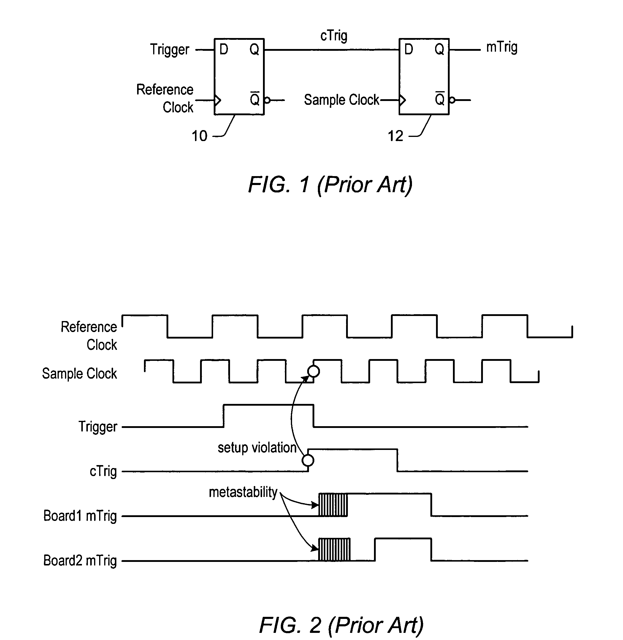
Even though choosing the sample clock frequency to be an integer multiple of a common reference signal may result in sample clocks that are in phase from device to device (subject to various component and routing tolerances), it may not necessarily achieve a desired type of synchronization (e.g., digital synchronization).
In systems where the set of devices have sample clock frequencies that are not integer multiples of the sample clock frequency, achieving digital synchronization may be even more difficult.
However, rising edges on the reference clock may not correspond to rising edges on the sample clock since the frequency of the sample clock is not an integer multiple of the reference clock.
However, clocking trigger signals with the reference clock signal may not ensure that two devices will see the trigger assertion in the same sample clock cycle.
As FIG. 2 shows, output cTrig of the first flip-flop 10 may change too close to the rising edge of the sample clock, causing a setup violation because the input to the second flip-flop has not been stable for the necessary setup time.
Thus, synchronization may be difficult when the sample clock frequency is not an integer multiple of the reference clock frequency.
However, depending upon the complexity of the instrumentation system, the number of function calls required to synchronize multiple instruments may be quite large, and the calling order of the function calls may be quite complex.
Additionally, function calls must generally be made manually to device drivers for each of the instruments, and thus the synchronization process may be tedious and error prone.

Method used


Image

  • Application programming interface for synchronizing multiple instrumentation devices
  • Application programming interface for synchronizing multiple instrumentation devices
  • Application programming interface for synchronizing multiple instrumentation devices

Examples


example attributes

[0187]As noted above, the attributes included in the API are preferably on a per session basis, i.e., each session has an associated set of attributes. Below are more detailed descriptions of the exemplary attributes mentioned above.

[0188]

TCLK_ATTR_SYNC_PULSE_SRC

[0189]In one embodiment, the TCLK_ATTR_SYNC_PULSE_SRC attribute (or equivalent) is used to specify the source of the sync pulse, and may be used primarily when synchronizing a multi-chassis system. Access for the attribute is read / write, and in one embodiment, the attribute has a string data type (e.g., ViString) for reading, and a constant string data type (e.g., ViConstString) for writing.

[0190]In one embodiment, for example, iin a PXI implementation, the attribute may specify the sync pulse source with the following values: for a module in any slot connected to the PXI backplane, “PXI_Trig0” through “PXI_Trig7”; in addition, for modules in slots 3 through 15 of the PXI chassis, “PXI_Star”.

[0191]In one embodiment, front pa...

example c programs

for Performing Synchronization

[0245]The following are example programs in C respectively illustrating synchronization of multiple instruments using prior art techniques and using an embodiment of the present API.

[0246]

C Program Using Traditional API#define sessionCount 10 / / assume 10 sessions are being synchronizedint sessions[sessionCount];double lockTime[sessionCount];double lockConfirmTime[sessionCount];double meas[sessionCount];char syncCmnd[500];int i;statusWrap(traditional_dsgnCmndSession(session[0]));statusWrap(traditional_getTimingEngineName(session[0], syncCmnd));strcat(syncCmnd, “ / syncCmnd”);for (i=0; istatusWrap(traditional_setSyncCmndSrc(session[i], syncCmnd));for (i=0; i{statusWrap(traditional_getPLLLockTime(session[i], lockTime[i]));statusWrap(traditional_getPLLLockConfirmTime(session[i],lockConfirmTime[i]));statusWrap(traditional_prepareToResetPLL(session[i]));}statusWrap(traditional_issueResetPLLCmnd(session[0]));wait(max(sessionCount, lockTime)); / / assume wait and ...


PUM


Abstract

An application programming interface (API) for synchronizing multiple devices in a system. The API includes a plurality of functions invocable in a program to synchronize multiple devices, where each function is executable to perform a respective functionality related to synchronizing the devices, and at least one of the functions is executable to access a plurality of instrument drivers corresponding respectively to the plurality of devices to synchronize the plurality of devices. In synchronizing the plurality of devices, the functions determine a trigger clock signal for each of the plurality of devices, and synchronize the plurality of devices based on the determined trigger clock signals. The API also includes a plurality of attributes corresponding to respective properties of the system related to synchronization of the devices, including one or more trigger attributes and / or one or more trigger clock attributes for each of the devices. The API representations may be text-based and / or graphical.

Description

FIELD OF THE INVENTION[0001]This invention relates to instrumentation systems and, more particularly, to an application programming interface (API) for synchronizing instrumentation devices, where the API may be text-based and / or graphical.DESCRIPTION OF THE RELATED ART[0002]Traditionally, high level text-based programming languages have been used by programmers in writing application programs. Many different high level text-based programming languages exist, including BASIC, C, C++, Java, FORTRAN, Pascal, COBOL, ADA, APL, etc. Programs written in these high level text-based languages are translated to the machine language level by translators known as compilers or interpreters. The high level text-based programming languages in this level, as well as the assembly language level, are referred to herein as text-based programming environments.[0003]Increasingly, computers are required to be used and programmed by those who are not highly trained in computer programming techniques. Whe...

Claims


Application Information

Patent Timeline
Patent Type & Authority Patents(United States)
IPC IPC(8): G01M19/00G01M99/00G06F9/46
CPCG05B19/042
Inventor ILIC, KOSTABARTZ, CHRISTOPHER T.
Owner NATIONAL INSTRUMENTS
Why Eureka
Try Eureka