Adaptable control plane architecture for a network element

a network element and control plane technology, applied in data switching networks, frequency-division multiplexes, instruments, etc., can solve the problems of central control networks suffering from performance and reliability problems, putting an inordinate amount of workload on the central control system, etc., to ensure the compatibility of the control plane features of network elements

Active Publication Date: 2008-01-01
RPX CORP
View PDF4 Cites 74 Cited by
  • Summary
  • Abstract
  • Description
  • Claims
  • Application Information

AI Technical Summary

Benefits of technology

[0013]The present invention provides a method, computer program product, and data processing system for distributed control of network elements in a manner that is scalable, adaptable, and platform-independent. The present invention divides the control plane functions of a network element into subsystems, which are implemented as processes or threads. A bus-like messaging framework allows the subsystems to communicate with each other. Under the messaging framework, subsystems can communicate with each other without regard for whether the subsystems reside on separate (possibly heterogeneous) hardware platforms or on the same processor. This architecture allows individual components of the control plane functions of a single network element to be placed on different processors or on the same processor, depending on the desired degree of parallel processing or level of integration with low-level network-element hardware. Thus, the design of the present invention allows a system designer to scale the computational power of a network element to meet current needs, adapt disparate computing platforms to work together to control a single network element, and ensure compatibility of the control plane features of network elements with disparate hardware platforms.

Problems solved by technology

These centrally-controlled networks suffer from performance and reliability problems.
Central control creates a single point of failure and puts an inordinate amount of workload on the central control system when many connections must be established and terminated.

Method used


Image

  • Adaptable control plane architecture for a network element
  • Adaptable control plane architecture for a network element
  • Adaptable control plane architecture for a network element

Examples


Embodiment Construction

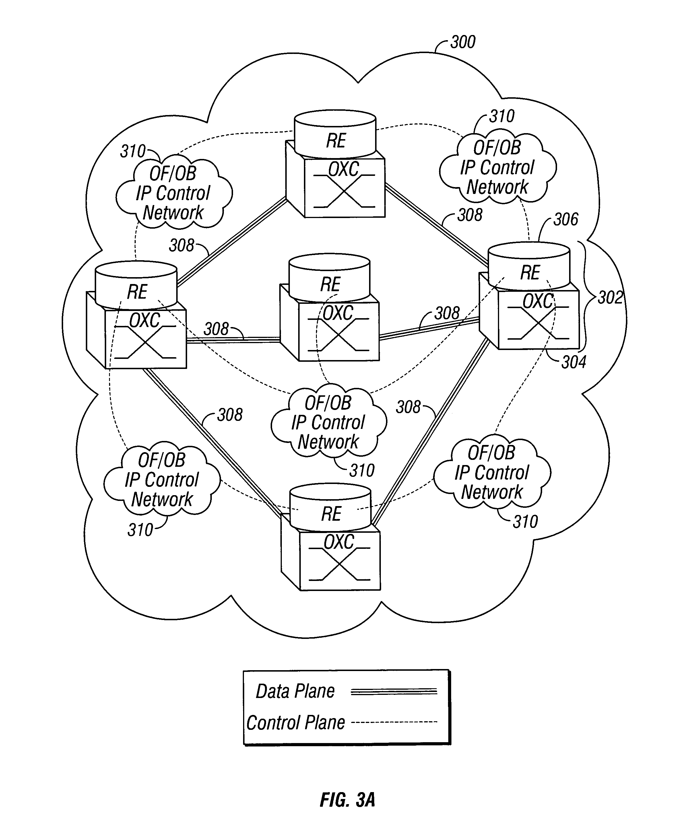
[0031]FIG. 3A is diagram of a network made in accordance with the preferred embodiment of the present invention. Network 300 is made up of a number of network elements, such as network element 302. Each of the network elements includes a transport network element 304 (which, in this case, is an optical cross connect (OXC)) and Routing Engine software 306. Optical cross connect 304 allows incoming data from optical data links to be switched to outgoing optical data links. Thus, optical cross connect 304 allows for circuit switching of optical data signals. One of ordinary skill in the art will recognize, however, that the teachings of the present invention are not limited to optical networks or optical cross-connects, but may be applied to any form physical form of network or cross-connect, including digital cross-connects (DXCs).

[0032]Routing Engine software 306 provides control functions to network element 302. In particular, Routing Engine 306 is responsible for routing path calcu...


PUM


Abstract

A method, computer program product, and data processing system for distributed control of network elements is disclosed. The present invention divides the control plane functions of a network element into subsystems, which are implemented as processes or threads. A bus-like messaging framework allows the subsystems to communicate with each other. Under the messaging framework, subsystems can communicate with each other without regard for whether the subsystems reside on separate (possibly heterogeneous) hardware platforms or on the same processor. This architecture allows individual components of the control plane functions of a single network element to be placed on different processors or on the same processor, depending on the desired degree of parallel processing or level of integration with low-level network-element hardware.

Description

CROSS REFERENCE TO RELATED APPLICATIONS[0001]This application claims the benefit of the filing date of corresponding U.S. Provisional Patent Application No. 60 / 410,808, entitled “GMPLS Routing Engine,” filed Sep. 13, 2002.BACKGROUND OF THE INVENTION[0002]1. Technical Field[0003]The present invention is related to control software for network elements. Specifically, the present invention provides a method, a computer program product, and a data processing system for platform-independent, adaptable control of a network element.[0004]2. Description of Related Art[0005]Modern telecommunications depends on networks. A network is a set of interconnected machines (network elements) that allow data to be relayed across the set of machines from a source to a destination. As the need for faster and more versatile telecommunications has increased, networks have evolved to accommodate that need. The automatically-switched telephone system replaced early manual switchboards. Digital telephony re...

Claims


Application Information

Patent Timeline
Patent Type & Authority Patents(United States)
IPC IPC(8): G06F15/16
CPCH04L12/24H04L41/00H04L45/00H04L45/50H04L45/56H04L45/60H04L49/90H04Q11/0062H04L41/0213H04L41/0663H04Q2011/0079
Inventor HARDEE, KEVIN MICHAELSOULAKIS, MICHAEL G.HAMBLETON, THOMAS WILEY
Owner RPX CORP
Why Eureka
Try Eureka