
Suction muffler for a hermetic refrigerant compressor

a technology of refrigerant compressor and suction muffler, which is applied in the direction of combustion-air/fuel-air treatment, positive displacement liquid engines, lighting and heating apparatus, etc. it can solve the problem of no pressure equalisation, and achieve the effect of facilitating the manufacturing of pipes and facilitating the manufacturing of housings

Active Publication Date: 2008-01-08
DANFOSS COMPRESSORS +1
View PDF13 Cites 33 Cited by
  • Summary
  • Abstract
  • Description
  • Claims
  • Application Information

AI Technical Summary

Benefits of technology

"The invention is about preventing too much oil from remaining in the refrigerant gas flow. The technical effect of the invention is to create a gas supply channel that allows for a pressure drop and equalization of pressure between the beginning and end of the channel, through an oil extraction opening. This allows for a suction muffler that can remove oil from the refrigerant gas flow, reducing the pressure drop and improving the efficiency of the refrigerant compressor. The oil extraction opening is formed by a gap between the housing and the inlet of the gas supply channel, which allows for a small amount of oil to pass through. The oil is then removed through an outlet nozzle located opposite the end of the gas supply channel, which keeps the stay duration of the refrigerant gas in the suction muffler small. The gas supply channel is located in a closed pipe, which facilitates manufacturing. The pipe has outwardly projecting lugs for fixing in the housing. The oil drip-off edge prevents separated oil from getting back into the refrigerant flow."

Problems solved by technology

However, it permits no pressure equalisation between the beginning of the gas supply channel and the inside of the muffling chamber.

Method used


Image

  • Suction muffler for a hermetic refrigerant compressor
  • Suction muffler for a hermetic refrigerant compressor
  • Suction muffler for a hermetic refrigerant compressor

Examples


Embodiment Construction

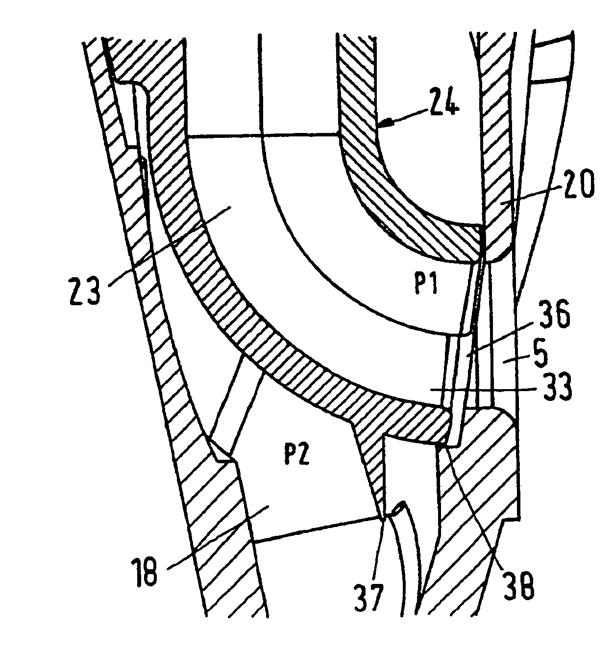
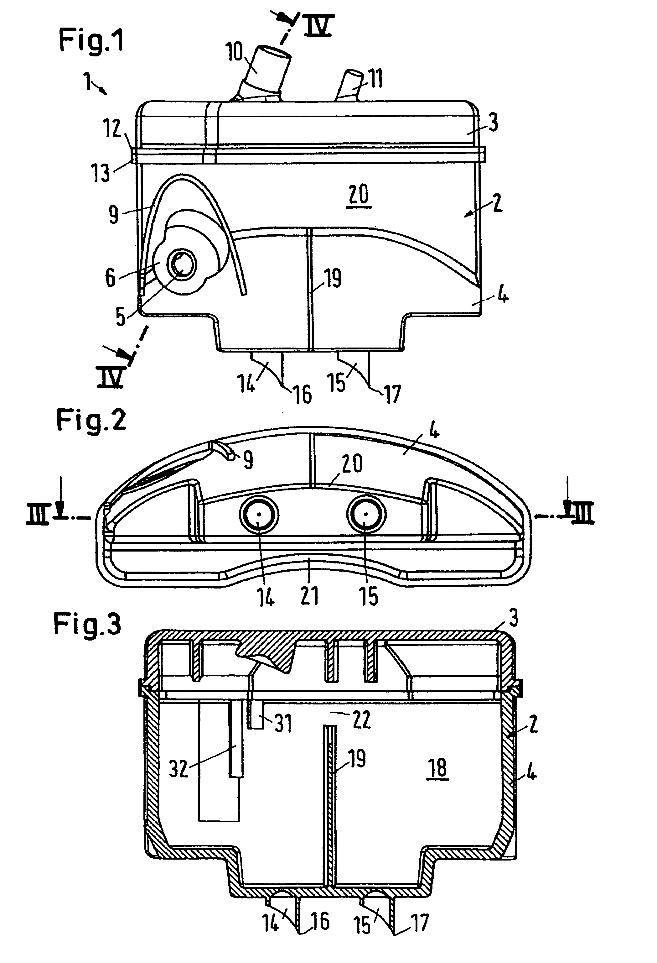
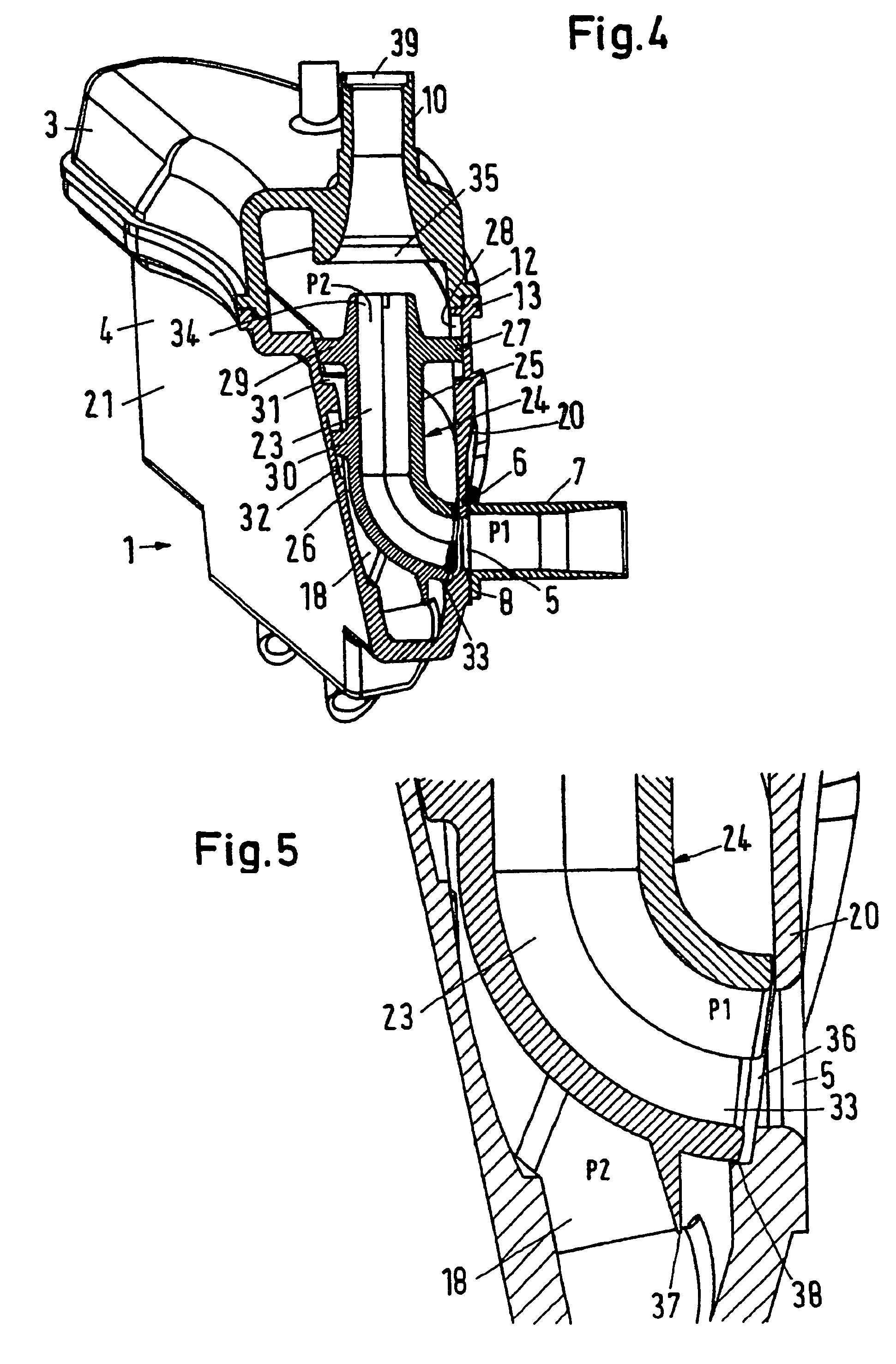
[0028]A suction muffler 1 has a housing 2, which is formed by a top part 3 and a bottom part 4. The bottom part has an inlet 5 in the form of an opening in the wall of the housing 2. The inlet 5 is surrounded by a plane bearing surface 6, on which a supply line 7 (FIG. 4) with a bearing flange 8 bears with a certain force. Between the supply line 7 and the suction muffler 1, a certain relative movement is possible without causing the closing of a passage between the supply line 7 and the inlet 5.

[0029]An oil shield 9 having the shape of an arch is located above the inlet 5. Oil, which settles on the outside of the housing and runs downwards under the influence of the gravity, is prevented from getting into the inlet 5 by the oil shield 9.

[0030]On its upper side the top part 3 has an outlet nozzle 10, on which a connection line to the compressor stage of a refrigerant compressor can be fixed in a manner not shown in detail. Further, a mounting lug 11 is provided, which can be used fo...


PUM


Abstract

The invention concerns a suction muffler for a hermetic refrigerant compressor with a housing having an inlet and an outlet and limiting at least one muffling chamber, and a gas supply channel located in the muffling chamber between the inlet and the outlet. It is endeavoured to prevent too much oil from remaining in the refrigerant gas flow. For this purpose, the gas supply channel forms a throttling path and ends in the muffling chamber, and that in the area of the inlet of the gas supply channel an oil extraction opening is located, which ends in the muffling chamber.

Description

CROSS-REFERENCE TO RELATED APPLICATIONS[0001]This application is entitled to the benefit of and incorporates by reference essential subject matter disclosed in German Patent Application No. 103 23 526.4 filed on May 24, 2003.FIELD OF THE INVENTION[0002]The invention concerns a suction muffler for a hermetic refrigerant compressor with a housing having an inlet and an outlet and limiting at least one muffling chamber, and a gas supply channel located in the muffling chamber between the inlet and the outlet.BACKGROUND OF THE INVENTION[0003]Such a suction muffler is, for example, known from DE 195 22 383 A1. The gas supply channel is guided between two walls, which do not completely fill a clearance between two inner housing walls. Accordingly, the gas supply channel is connected with the muffling chamber over practically its whole length.[0004]DE 199 23 734 C2 shows another suction muffler for a hermetically enclosed compressor, in which the muffling chamber is divided into two subcha...

Claims


Application Information

Patent Timeline
Patent Type & Authority Patents(United States)
IPC IPC(8): F02M35/00F04B39/00
CPCF04B39/0061Y10S181/403
Inventor THOMSEN, JANBJERRE, PREBENSVENDSEN, CHRISTIANSVENDSEN, MORTENREINWAND, KLAUS
Owner DANFOSS COMPRESSORS
Learn More