
System and method for delivering cryogenic fluid

a technology of fluid delivery system and fluid delivery method, which is applied in the direction of container discharging method, container discharging from pressure vessels, pressure vessels, etc., can solve problems such as water jet machining problems

Active Publication Date: 2008-01-08
IHI CORP
View PDF14 Cites 45 Cited by
  • Summary
  • Abstract
  • Description
  • Claims
  • Application Information

AI Technical Summary

Benefits of technology

The present invention provides a rotating nozzle assembly for delivering cryogenic fluid at high pressure and velocity for cutting or machining materials. The assembly includes a seal and a seal backup disk to prevent the cryogenic fluid from leaking. The system is efficient and does not produce secondary waste. It can be used in medical applications and also in cold spraying for sandblasting or replacing electroplating.

Problems solved by technology

However, water jet machining may suffer from problems relating to the collection of the water during the machining operation or problems relating to the potential contamination of the water or surrounding environment from the material removed from the workpiece.

Method used


Image

  • System and method for delivering cryogenic fluid
  • System and method for delivering cryogenic fluid
  • System and method for delivering cryogenic fluid

Examples


Embodiment Construction

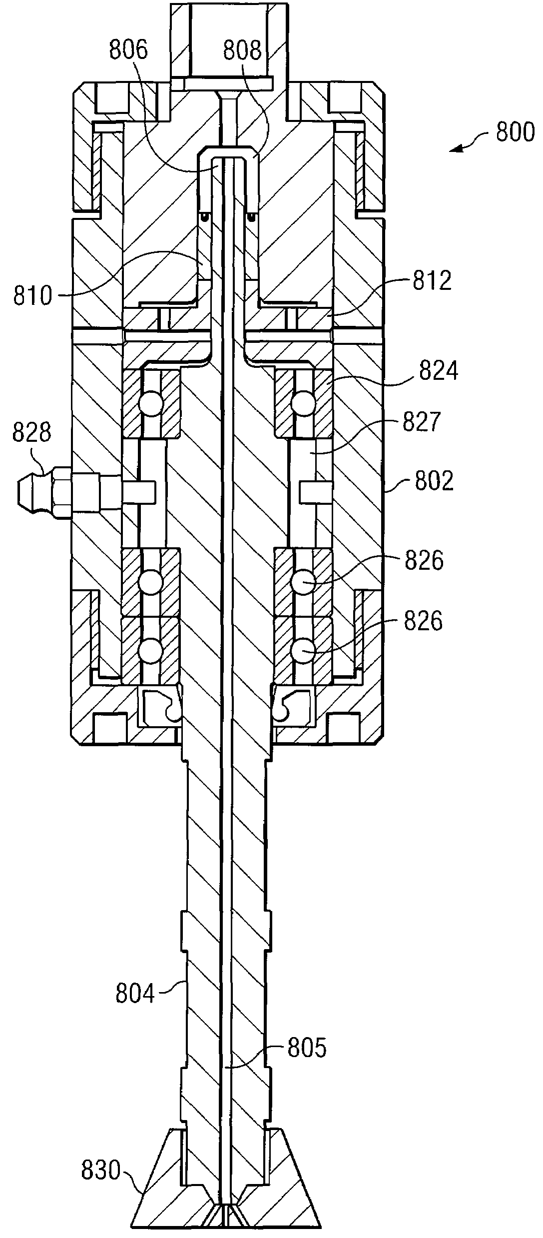
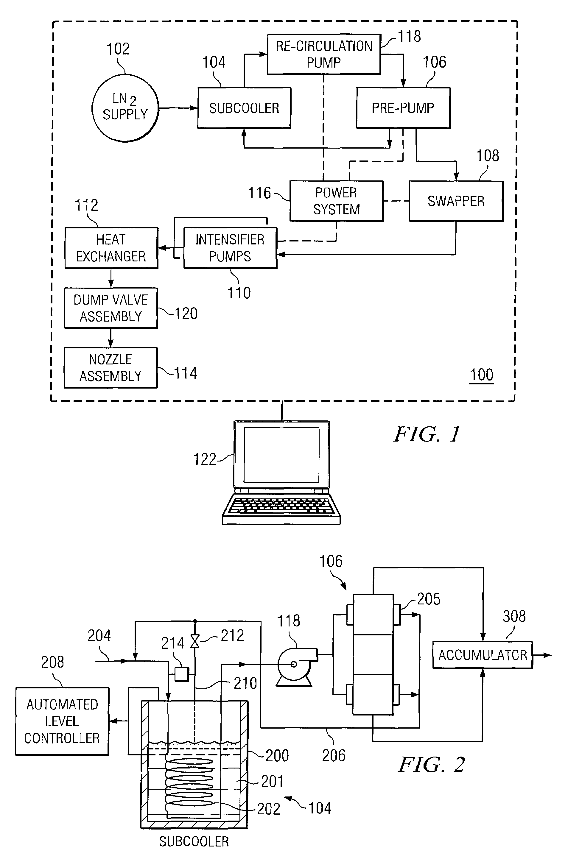
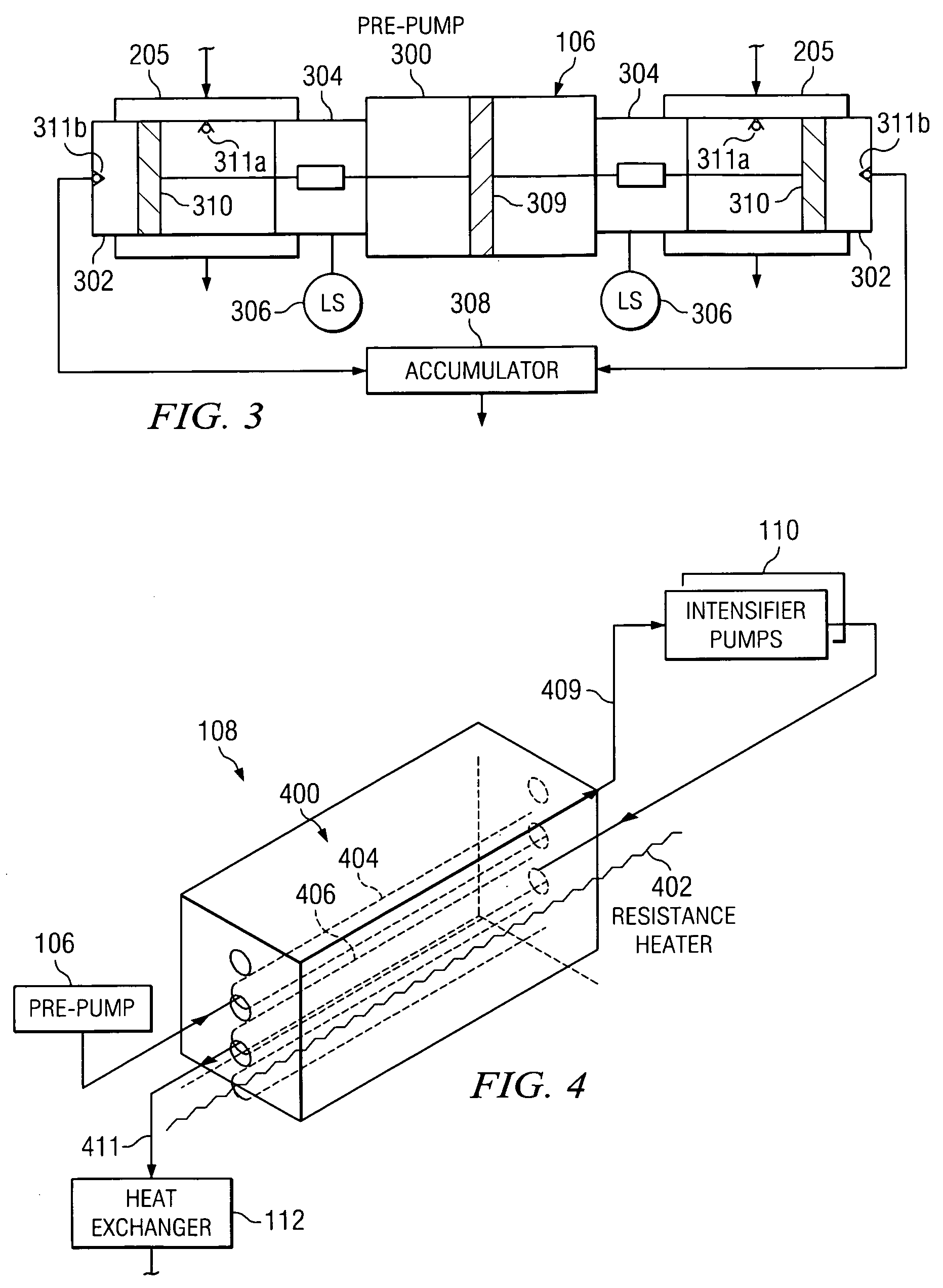
[0018]Embodiments of the present invention and some of their advantages are best understood by referring to FIGS. 1 through 9B of the drawings, like numerals being used for like and corresponding parts of the various drawings.

[0019]FIG. 1 is a functional block diagram of a cryogenic fluid delivery system 100 according to one embodiment of the present invention. In the illustrated embodiment, delivery system 100 includes a liquid nitrogen supply 102, a sub-cooler 104, a pre-pump 106, a swapper 108, a pair of intensifier pumps 110, a heat exchanger 112, a nozzle assembly 114, a power system 116, a recirculation pump 118, a dump valve assembly 120, and a controller 122. The present invention, however, contemplates delivery system 100 having more, less, or different components than those illustrated in FIG. 1. Generally, cryogenic fluid delivery system 100 provides a cryogenic fluid stream capable of high pressure and high velocity in order to cut, abrade, or otherwise suitably machine ...


PUM

PropertyMeasurementUnit
diameteraaaaaaaaaa
diameteraaaaaaaaaa
pressureaaaaaaaaaa

Abstract

According to an embodiment of the present invention, a rotating nozzle assembly includes a rotatable shaft having a bore to transport a cryogenic fluid therethrough. The rotatable shaft has an upstream portion associated with a feed chamber and a downstream portion. The nozzle assembly further includes a seal disposed within the feed chamber and surrounding at least a portion of the rotatable shaft, and a seal backup disk disposed proximate the seal. The seal backup disk includes an orifice surrounding an outside diameter of the rotatable shaft, the orifice having a diameter such that, when the cryogenic fluid is flowing through the bore of the rotatable shaft, the rotatable shaft can freely rotate while the seal prevents the cryogenic fluid from seeping past the seal.

Description

TECHNICAL FIELD OF THE INVENTION[0001]This invention relates in general to fluid dynamic machining and, more particularly, to a system and method for delivering a cryogenic fluid.BACKGROUND OF THE INVENTION[0002]In fluid dynamic machining the force resulting from the momentum change of the fluid stream is utilized to cut, abrade, or otherwise machine materials. For example, water is often used as a fluid to cut or abrade certain materials and various abrasive materials may be used to enhance material removal. However, water jet machining may suffer from problems relating to the collection of the water during the machining operation or problems relating to the potential contamination of the water or surrounding environment from the material removed from the workpiece.[0003]To address the foregoing problems, sublimable particles, such as dry ice, may be used as the cutting material. The primary advantage of using sublimable particles is that there is no secondary waste material to be ...

Claims


Application Information

Patent Timeline
Patent Type & Authority Patents(United States)
IPC IPC(8): B05B3/16B05B3/04F17C7/02
CPCB05B1/14B05B3/001B05B3/02B05B3/026B05B7/1486B24C1/003
Inventor HUME, HOWARD R.WARNECKE, RONALD R.PALMER, GARY L.FEKETE, LESLIE J.
Owner IHI CORP
Learn More