Pressed-connection arrangement

a technology of pressing connection and sealing ring, which is applied in the direction of fluid pressure sealing joints, sleeves/socket joints, pipe joints, etc., can solve the problems of reducing the service life of the receiving device. , to achieve the effect of reducing the cost of the connection piece, reducing the risk of deformation of the already produced first receiving device, and reducing the cos

Active Publication Date: 2008-01-08
VIEGA TECH GMBH & CO KG
View PDF48 Cites 76 Cited by
  • Summary
  • Abstract
  • Description
  • Claims
  • Application Information

AI Technical Summary

Benefits of technology

[0007]Further, according to the present disclosure, a separating ring is provided between the sealing ring and the cutting ring, by which separating ring the cutting ring is held at a distance from the sealing ring. As a result, only a single ring-shaped receiving device has to be shaped out at the connection piece, in which receiving device the sealing ring, the separating ring and the cutting ring will then be held. The arrangement of a separating ring between the sealing ring and the cutting ring represents a simplification in comparison to the separate construction of receiving devices. By the separating ring, it is ensured that, during the pressing-together, the sealing ring is not damaged by the cutting ring, and a durable sealing-off can therefore be ensured.
[0008]According to an embodiment of the present disclosure; the sealing ring, the separating ring and the cutting ring are held in a prefixed manner as a preassembled unit in the essentially U-shaped receiving device before a pressing-together. In addition, the receiving device may have two inward-extending legs and the preassembled unit is thus held in a secured manner in the axial direction and cannot be lost during transport. Furthermore, the arrangement of the individual components cannot accidentally be confused.

Problems solved by technology

The providing of a receiving device for the sealing ring and of a receiving device for the cutting ring requires comparatively high expenditures.
It is difficult to produce the connection piece by a forming method because, when the second receiving device is produced, there is the risk that the already produced first receiving device will be deformed again.
There is the risk that, during the pressing-together of the connection, the sealing ring may be damaged and its tightness can therefore not be guaranteed.
In addition, the cutting ring is situated on the side facing the pipe end in the hydraulically guided area, so that a contamination of the piping system by the cutting ring cannot be excluded.

Method used


Image

  • Pressed-connection arrangement
  • Pressed-connection arrangement
  • Pressed-connection arrangement

Examples


Embodiment Construction

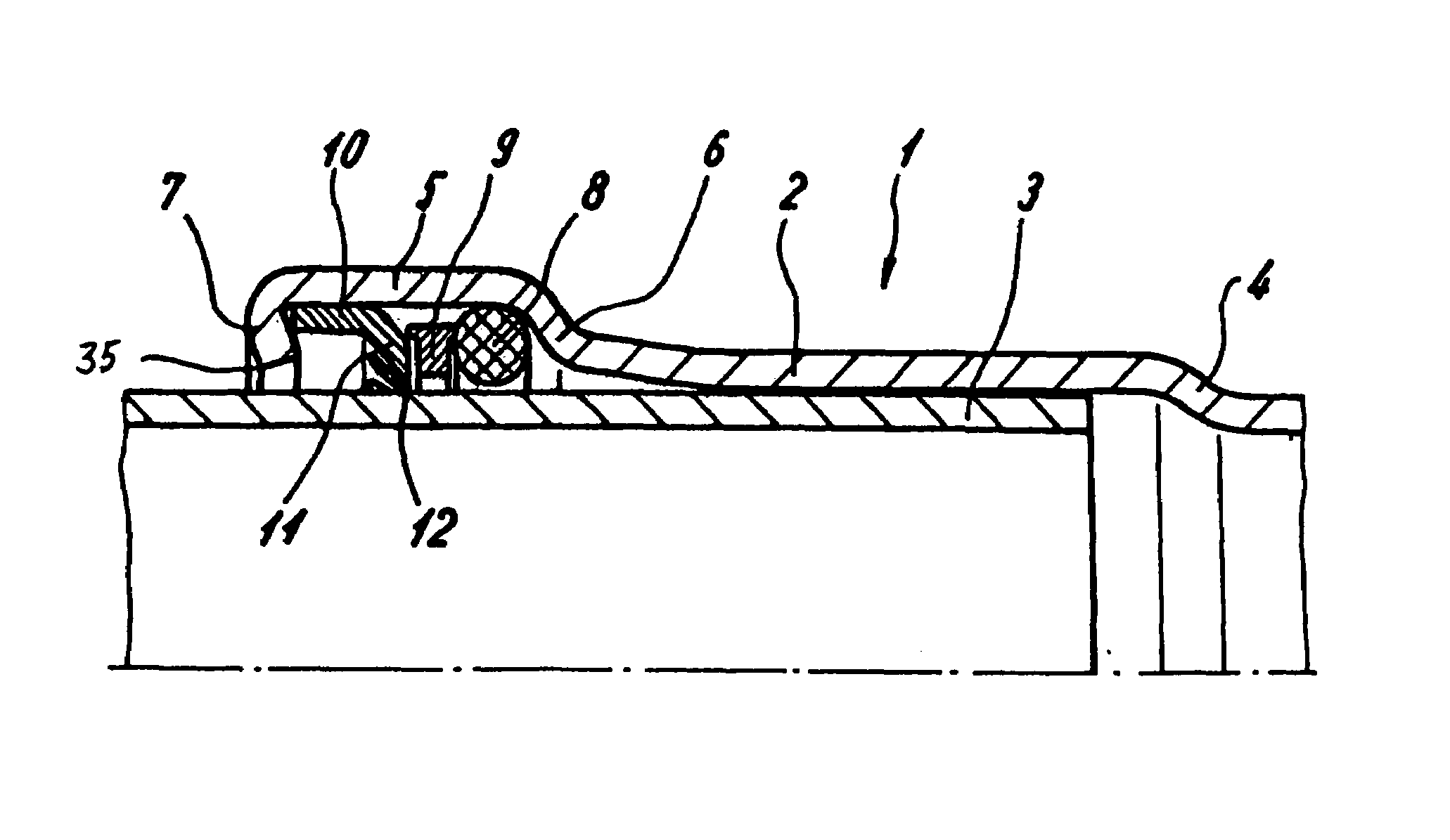
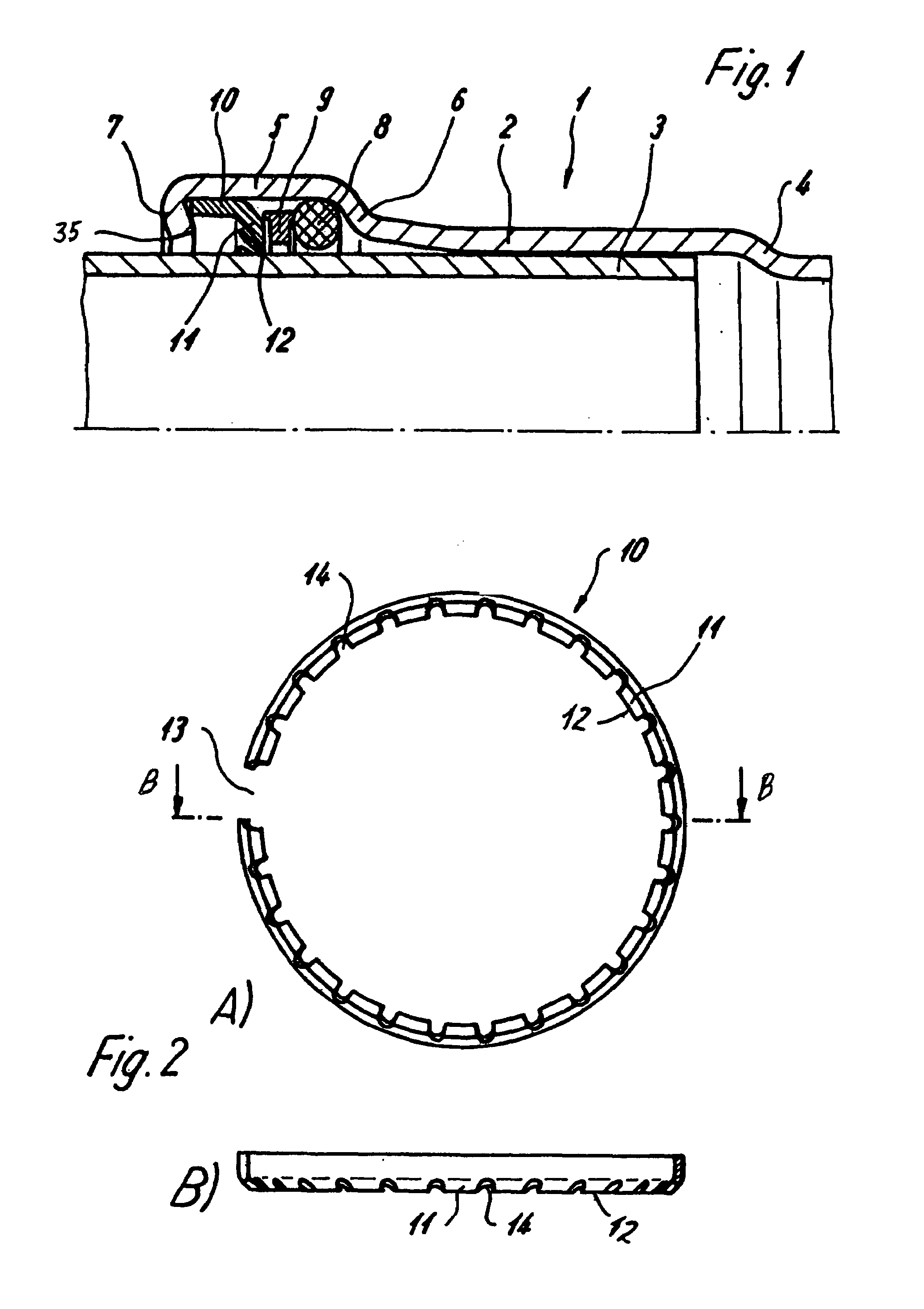
[0024]As shown in FIG. 1, a pressed-connection arrangement 1 comprises a fitting or connection piece 2 which may be made of a metal, such as copper, steel or another metal alloy. A first pipe end 3, which may also be made of metal, is inserted into the connection piece 2. It is conceivable that the pipe end 3 may be made of a composite material which is then reinforced, for example, by a supporting sleeve (not shown). The pipe end 3 can be pushed into the connection piece 2 up to a stop 4 which is formed by a slight radial tapering of the connection piece 2.

[0025]A receiving device 5 is constructed on an end side of the connection piece 2, which receiving device 5 has a diameter which is enlarged in comparison to a remaining portion of connection piece 2. The receiving device 5 has an essentially U-shaped cross-section as well as an end-side leg 7 and a leg 6 facing the remaining portion of connection piece 2.

[0026]A prefixed or preassembled unit including a sealing ring 8, a separa...


PUM


Abstract

A pressed connection arrangement including a first pipe end and a connection piece configured to receive the pipe end. The connection piece has a ring-shaped receiving device and the ring-shaped receiving device includes a cutting ring and a sealing ring. A separating ring is located between the sealing ring and the cutting ring such that the separating ring holds the cutting ring at a distance from the sealing ring.

Description

[0001]This application claims benefit of German Application 20 2004 007 291.2 filed May 7, 2004, which disclosure is hereby incorporated by reference herein.BACKGROUND AND SUMMARY[0002]The present disclosure relates to a pressed-connection arrangement having a connection piece. The connection piece may be made of a cold-workable material, which is constructed on a fitting or a valve and into which a pipe end can be pushed. The connection piece has a ring-shaped receiving device in which a metallic cutting ring and a sealing ring are held.[0003]From German Patent Document DE 297 21 760, a pressed connection between a fitting and a metal pipe end is known. A receiving device for a sealing ring and a spaced receiving device for a cutting ring is provided on the fitting. A pipe end is pushed into the connection piece, and a radial pressing-together is then carried out in order to establish a sealed-off connection, the cutting ring providing a mechanical fixing of the pipe end. The provi...

Claims


Application Information

Patent Timeline
Patent Type & Authority Patents(United States)
IPC IPC(8): F16L19/06F16L19/08F16L21/08F16L13/14
CPCF16L13/142F16L37/091
Inventor VIEGENER, WALTER
Owner VIEGA TECH GMBH & CO KG
Why Eureka
Try Eureka