Circuit and method for driving a liquid crystal display device using low power

a liquid crystal display device and low power technology, applied in the field of display devices, can solve the problems of increasing the whole power consumption of the lcd driver circuit and unnecessarily consuming power, and achieve the effect of reducing power consumption

Inactive Publication Date: 2008-01-08
SAMSUNG ELECTRONICS CO LTD
View PDF16 Cites 23 Cited by
  • Summary
  • Abstract
  • Description
  • Claims
  • Application Information

AI Technical Summary

Benefits of technology

[0023]Accordingly, the present invention provides a driver circuit, for driving an LCD device,

Problems solved by technology

Therefore, a bias current of a more than admissible value flows in the driver amplifier, which results in an increase in the whole power consumption of an LCD driver circuit.
Sin

Method used


Image

  • Circuit and method for driving a liquid crystal display device using low power
  • Circuit and method for driving a liquid crystal display device using low power
  • Circuit and method for driving a liquid crystal display device using low power

Examples


Embodiment Construction

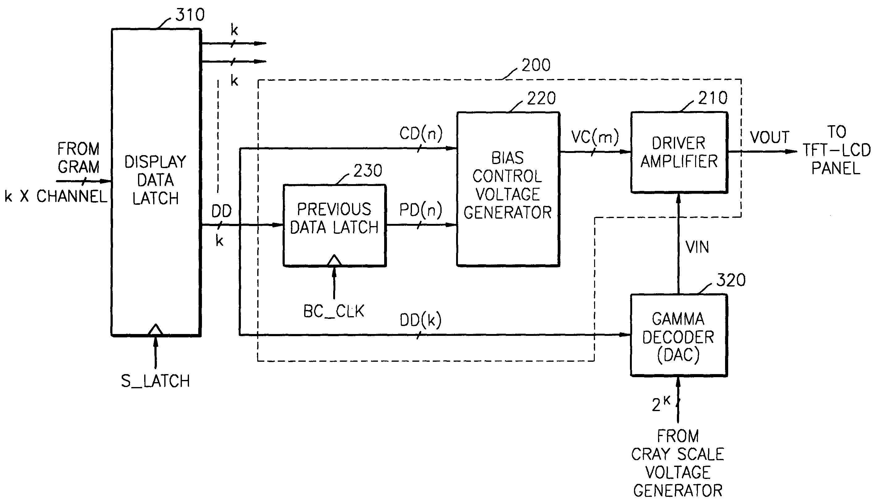
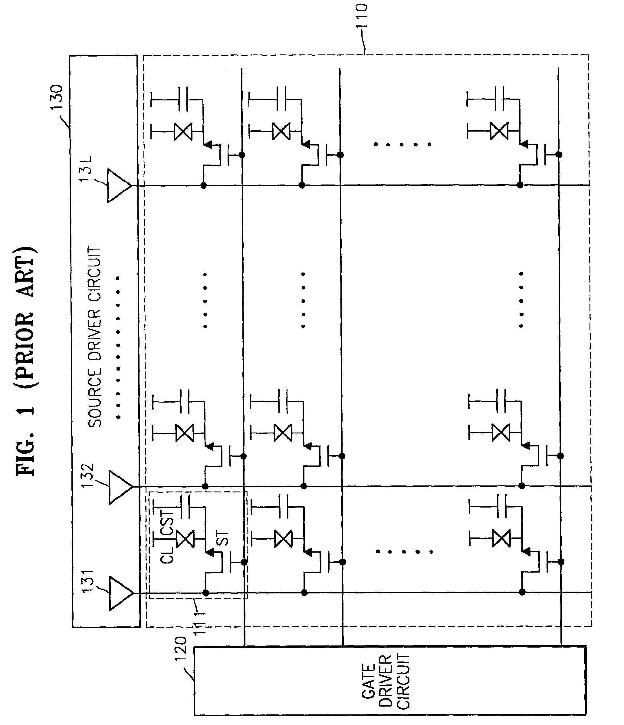
[0046]FIG. 5 is a schematic view of a driver cell, a slew rate of which is adaptively controlled according to an embodiment of the present invention. The driver cell corresponds to the driver amplifiers 131 through 13L, which are actually ends of channels for liquid crystal in the source driver circuit 130 shown in FIG. 1. The driver cell is installed in each channel. However, the driver cell of the present invention is not a circuit having only a general driver amplifier, but a driver circuit having a driver amplifier whose slew rate is controlled and an additional circuit for controlling the slew rate.

[0047]Referring to FIG. 5, a driver cell 200, a slew rate of which is adaptively controlled, according to an embodiment of the present invention includes a driver amplifier 210 and a bias control voltage generator 220.

[0048]The driver amplifier 210 amplifies or buffers an input voltage VIN to generate an output voltage VOUT which will be applied to a liquid crystal panel (not shown)....


PUM


Abstract

Provided are a circuit and method for driving a liquid crystal display device using low power. The circuit includes a display data latch, a gamma decoder, and a driver cell circuit. The display data latch latches display data from a memory. The gamma decoder receives a plurality of gray scale voltages, and selects and outputs one of the plurality of gray scale voltages in response to the display data. The driver cell circuit receives an output voltage of the gamma decoder and generates an output voltage applied to the liquid crystal display device. The driver cell circuit controls a slew rate in response to comparison result of current data and previous data of the display data. The driver cell circuit includes a previous data latch, a bias control voltage generator, and a driver amplifier. The previous data latch receives a portion or the whole of the display data and outputs the portion or the whole of the display data as the previous data. The bias control voltage generator compares the current data and the previous data of the display data and generates a control signal. The driver amplifier receives the output voltage of the gamma decoder, generates the output voltage applied to the liquid crystal display device, and controls the slew rate in response to the control signal.

Description

BACKGROUND OF THE INVENTION[0001]This application claims the priority of Korean Patent Application No. 2002-49295 filed on Aug. 20, 2002 in the Korean Intellectual Property Office, the contents of which are incorporated herein in their entirety by reference.[0002]1. Field of the Invention[0003]The present invention relates to a display device, and more particularly, to a method and circuit for driving a panel of a thin film transistor liquid crystal display device using low power.[0004]2. Description of the Related Art[0005]A circuit for driving a thin film transistor (hereinafter referred to as a TFT) liquid crystal display (hereinafter referred to as an LCD) device is generally classified into a gate driver circuit and a source driver circuit.[0006]FIG. 1 is a view of a general TFT-LCD device. Referring to FIG. 1, the general TFT-LCD device includes a liquid crystal panel 110, a gate driver circuit 120, and a source driver circuit 130.[0007]The liquid crystal panel 110 includes a ...

Claims


Application Information

Patent Timeline
IPC IPC(8): G09G3/36G06F3/038G09G5/00G02F1/133G09G3/20H03F1/02
CPCG09G3/3688G09G2300/0842G09G2330/021G09G2320/0252G09G2310/027G09G3/36
Inventor CHUNG, KYU-YOUNG
Owner SAMSUNG ELECTRONICS CO LTD
Why Eureka
Try Eureka