Active acoustic noise reduction system

a noise reduction and active technology, applied in the field of noise reduction systems, can solve the problems of large physical dimensions of the cancellation system, large group delay of the system, and high implementation and calibration costs of the noise reduction system made according to the prior art techniques described above, so as to reduce the effect of oscillation, and reduce the effect of echo

Inactive Publication Date: 2008-01-08
SILENTIUM LTD
View PDF28 Cites 67 Cited by
  • Summary
  • Abstract
  • Description
  • Claims
  • Application Information

AI Technical Summary

Benefits of technology

[0025]In addition to sensing sound from the noise source, the system also detects the sound from the output actuator. The portion of the input signal that is due to the output actuator is removed using an echo cancellation technique. If the output and input transducers are acoustically separate elements and there exists acoustic delayed feedback in the system, then using an echo cancellation system is preferred. Another advantage of the echo cancellation system is the elimination of feedback sound emanating from walls, furniture, etc. and sensed by the input transducer. If there is no delayed time feedback from the output transducer to the input transducer and a directional input transducer is used, then a computation may be performed on the input signal, instead of using an echo cancellation system, to discern the actual noise signal from the input signal.
[0027]There is therefore provided in accordance with the present invention an acoustic noise reduction system for reducing the effects of a noise source, comprising input transducer means for sensing the acoustic noise field generated by the noise source and for generating an input signal therefrom, output actuator means for generating an acoustic output field that is effective to reduce the level of the acoustic noise field, correction means for adjusting the input signal generated by the input transducer to compensate for the non linear characteristics of the input transducer and output actuator, echo cancellation means for removing from the input signal a portion of the output of the output actuator means fed back through the input transducer means, the output of the echo cancellation means representing a signal corresponding to substantially the noise source by itself, antinoise means for generating an antinoise signal opposite in phase to the input signal, the output actuator means generating the acoustic output field from the antinoise signal and wherein the input transducer means is located in relatively close proximity to the output actuator means.
[0028]There is also provided in accordance with the present invention an acoustic noise reduction system for reducing the effects of a noise source, comprising input transducer means for sensing the acoustic noise field generated by the noise source and for generating an input signal therefrom, output actuator means for generating an acoustic output field that is effective to reduce the level of the acoustic noise field, correction means for adjusting the input signal generated by the input transducer to compensate for the non linear characteristics of the input transducer, input decoding means for removing extraneous signals from the input signal so as to generate a signal corresponding to substantially the noise source alone, antinoise means for generating an antinoise signal opposite in phase to the input signal, the output actuator means generating the acoustic output field from the antinoise signal and wherein the input transducer means is located in relatively close proximity to the output actuator means.
[0033]The system further comprises a low pass filter operative to reduce oscillations present in the system derived from feedback of the acoustic output field to the input transducer. Also, the system further comprises delay cancellation means for reducing the effect of echo signals caused by the antinoise means sensed by the input transducer. The delay cancellation means comprises a plurality of delay cancellation circuits wherein each delay cancellation circuit is operative to reduce the effect of the echo caused by previous delay cancellation circuits.
[0034]Further, there is provided in accordance with the present invention a method for reducing the effects of a noise source, comprising the steps of sensing the acoustic noise field generated by the noise source and generating an input signal therefrom, generating an acoustic output field that is effective to reduce the level of the acoustic noise field, adjusting the input signal generated by an input transducer to compensate for the non linear characteristics of the input transducer and an output actuator, removing from the input signal a portion of the output of the output actuator fed back through the input transducer, generating a signal corresponding to substantially the noise source by itself and generating an antinoise signal opposite in phase to the input signal, generating the acoustic output field from the antinoise signal.
[0035]Also, there is provided in accordance with the present invention a method for reducing the effects of a noise source, comprising the steps of sensing the acoustic noise field generated by the noise source and for generating an input signal therefrom, generating an acoustic output field that is effective to reduce the level of the acoustic noise field, adjusting the input signal generated by an input transducer to compensate for the non linear characteristics of the input transducer, removing extraneous signals from the input signal so as to generate a signal corresponding to substantially the noise source alone and generating an antinoise signal opposite in phase to the input signal, the output actuator means generating the acoustic output field from the antinoise signal.

Problems solved by technology

This causes the group delay of the system to be relatively large.
The implementation and calibration of noise reduction systems made according to the prior art techniques described above are typically very difficult and correspondingly costly due to the need to supply a plurality of different elements, e.g., two microphones and a loudspeaker, and place these plurality of elements in their appropriate places.
Another disadvantage of prior art noise reduction systems is that if the canceled noise is not periodic in nature, then the physical dimensions of the cancellation system become relatively large.
When the loudspeaker is located far away from the noise source, then the noise cancellation is localized and limited to a relatively small area.

Method used


Image

  • Active acoustic noise reduction system
  • Active acoustic noise reduction system
  • Active acoustic noise reduction system

Examples


first embodiment

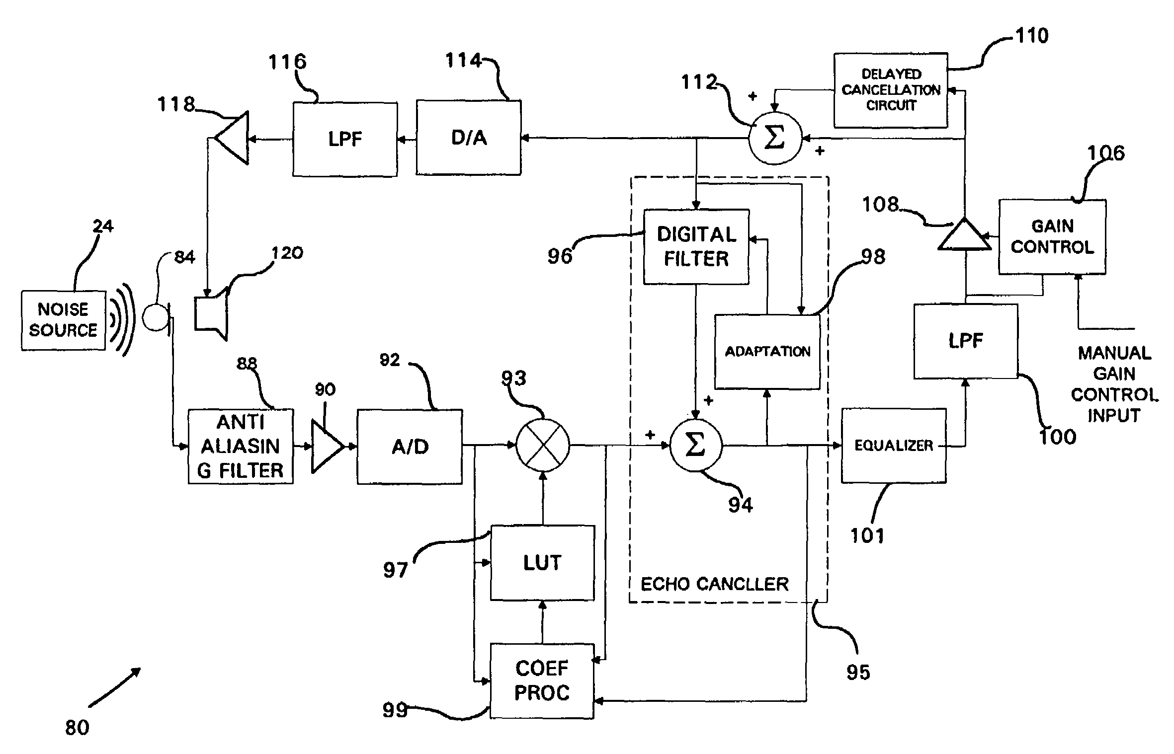
[0105]A high level flow diagram illustrating the first calibration method associated with the first embodiment is shown in FIG. 9. The first method of calibration utilizes the fact that the noise is physical and continuous. The controller in the system tracks the relationship between values termed Table Input (TI), Table Output (TO) and Summer Output (SO) during operation of the system. The TI values are measured at the output of the A / D converter 92 (FIG. 4), the TO values are measured at the output of the multiplier 93 and the SO values are measured at the output of the summer 94. The coefficient processor 99 functions to calculate new LUT coefficients based on the TI, TO and SO values.

[0106]The calibration of the LUT coefficients during operation of the system attempts to ignore the effects of the noise source. Note that the input noise source itself changes between two adjacent samples. Note also that the output of the summer SO represents the noise source since the echo cancele...

second embodiment

[0127]A high level flow diagram illustrating the first calibration method associated with the second embodiment is shown in FIG. 12. The first method of calibration utilizes the fact that the noise is physical and continuous. The controller in the system tracks the relationship between values termed Table Input (TI), Table Output (TO) and sigma (Σ) during operation of the system. The TI values are measured at the input to the LUT 184. The TO values are measured at the output of the multiplier 186. The Σ values are generated by the Σ generator 183. The coefficient processor functions to calculate new LUT coefficients based on the TI, TO and Σ values.

[0128]The calibration of the LUT coefficients during operation of the system attempts to ignore the effects of the noise source. Note that the input noise source itself changes between two adjacent samples. The calibration method measures two adjacent TO values at the output of the multiplier 93 (FIG. 11). Subsequently, the controller the...


PUM


Abstract

An active acoustic noise reduction system which comprises a single input transducer and an output actuator that are physically located next to each other in the same location. In one embodiment, the input transducer and the output actuator are a hybrid represented by a single element. The active noise reduction system is located as close as possible to the noise source and functions to generate an antinoise cancellation sound wave with minimum delay and opposite phase with respect to the noise source. The noise reduction system also comprises a non linearity correction circuit, a delayed cancellation circuit and variable gain amplifier. The system provides user control of the quiet zones generated by the system by varying the gain of the variable gain amplifier. The system provides a user with the ability In one embodiment, an echo canceler is utilized to remove echoes fed back from the output actuator. In another embodiment, an input decoder is used instead of an echo canceler to remove feedback picked up from the output actuator.

Description

CROSS-REFERENCE TO RELATED APPLICATIONS[0001]This application claims priority of Israeli Patent Application No. 121555, filed on Aug. 14, 1997.FIELD OF THE INVENTION[0002]The present invention relates generally to noise reduction systems and more particularly relates to acoustic noise reduction systems adapted to reduce the noise at a point relatively far from the noise source.BACKGROUND OF THE INVENTION[0003]Digital adaptive reduction of noise in the time domain is typically performed by sampling the analog output of a microphone that is appropriately positioned to sense the input noise. The sampled analog noise is then converted to digital format via an A / D converter, passed through an adaptive digital filter and then converted back to analog via a D / A converter before being output to a speaker. The analog output of a microphone is utilized as the input to the internal adaptive algorithm within the prior art noise reduction system.[0004]Since the group delay of such a system as de...

Claims


Application Information

Patent Timeline
Patent Type & Authority Patents(United States)
IPC IPC(8): A61F11/06G10K11/16H03B29/00H04B15/00G10KG10K11/178
CPCG10K11/1782G10K2210/12G10K2210/3039G10K2210/505G10K11/17813G10K11/17881G10K11/17857G10K11/17854G10K11/1785
Inventor AMIR, NEHEMIA
Owner SILENTIUM LTD
Why Eureka
Try Eureka