
Device and method for controlling trimming flaps on a watercraft, as well as a watercraft having a corresponding device

a technology for watercraft and flaps, which is applied in the direction of floating buildings, propulsive elements, vessel construction, etc., and can solve problems such as damage that must be repaired

Inactive Publication Date: 2008-01-15
BOENING AUTOMATIONSTECH
View PDF12 Cites 35 Cited by
  • Summary
  • Abstract
  • Description
  • Claims
  • Application Information

AI Technical Summary

Benefits of technology

"The invention is about controlling trimming flaps on a watercraft. The invention aims to determine the inclination angles of the trimming flaps in a way that is insensitive to defects and can automatically control the inclination angles in a simple way. The invention proposes using a hydraulic system with an associated flowmeter to detect the flow of hydraulic fluid and thus determine the inclination angle of the trimming flap. This allows for the position of the trimming flap to be controlled automatically without the need for wiring outside the hydraulic drive. The invention also provides a control unit to evaluate and influence the position of the trimming flap. Additionally, the invention proposes using a trimming curve stored in the control unit to automatically control the inclination angle of the trimming flap based on the speed of the watercraft or motor rotation speed. The invention simplifies the process of controlling the trimming flaps and makes it easier for users to adjust the inclination angle."

Problems solved by technology

One problem relating to the control of the inclination angles of the trimming flaps is, in particular, that the optimum inclination angle is dependent on the speed of the watercraft and must therefore be adapted by the user in order that the watercraft is as far as possible always aligned at an optimum attitude (preferably essentially flat) in the water.
It has been found that this procedure has certain disadvantages because appropriate position sensors or signal lines may be damaged during operation, which damage must be repaired, and this is costly.

Method used


Image

  • Device and method for controlling trimming flaps on a watercraft, as well as a watercraft having a corresponding device
  • Device and method for controlling trimming flaps on a watercraft, as well as a watercraft having a corresponding device
  • Device and method for controlling trimming flaps on a watercraft, as well as a watercraft having a corresponding device

Examples


Embodiment Construction

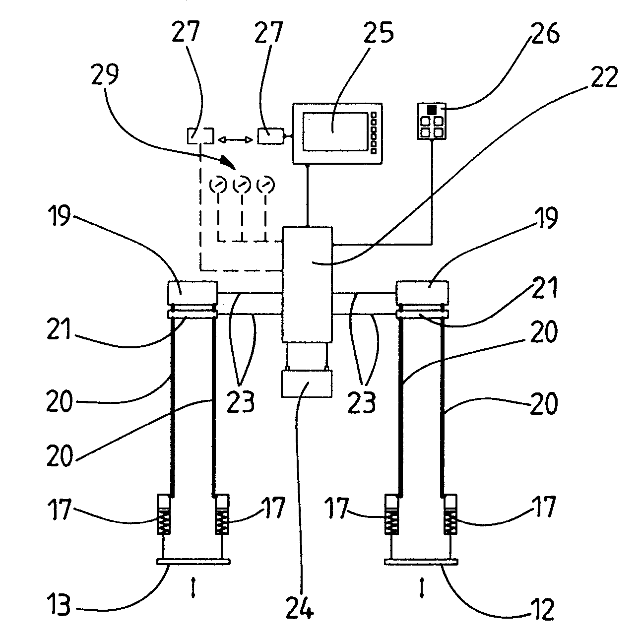
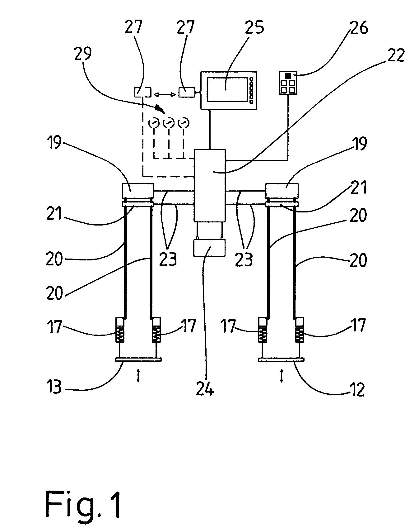
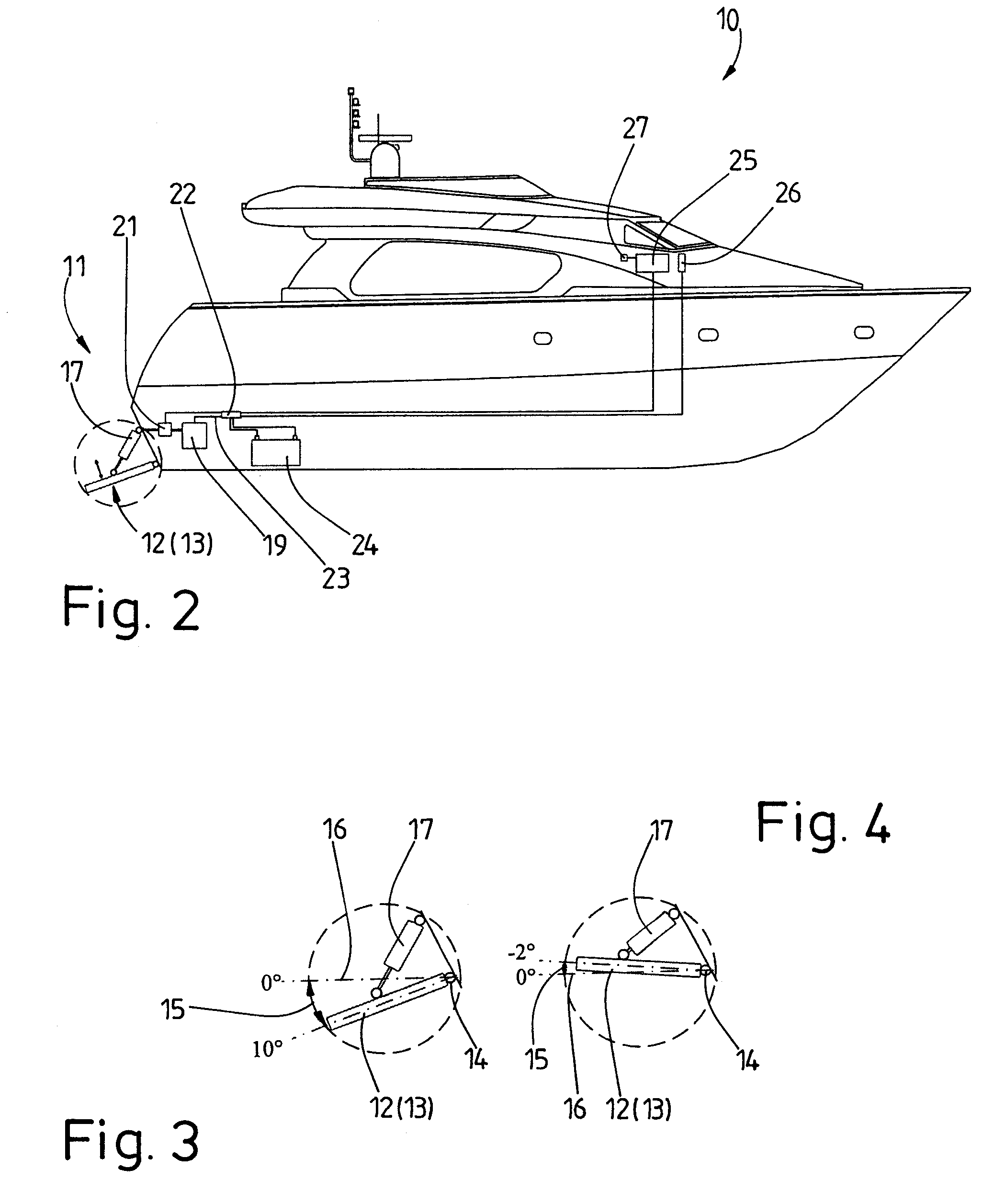
[0023]FIGS. 1 to 6 show one preferred embodiment of a system for controlling the inclination angle of trimming flaps on a watercraft. It is self-evident that the following description of the exemplary embodiment indicates only one of many options for implementation of the invention. In principle, departures may be made at individual points from the described solution without departing from the fundamental idea of the invention. The following description should in no way be regarded as any restriction to the scope of protection of the patent claims to the described exemplary embodiment.

[0024]FIG. 2 shows a side view of a watercraft 10. Two trimming flaps 12, 13 are arranged in the area of the stern 11 of the watercraft, to be precise a starboard trimming flap 12 and a port trimming flap 13.

[0025]In a plan view, the two trimming flaps 12, 13 are preferably arranged at the same distance laterally from the longitudinal center axis of the watercraft 10, which is not shown. The two trimmi...


PUM


Abstract

A device for controlling trimming flaps (12, 13) of a watercraft (10), preferably having two trimming flaps (12, 13) and in each case at least one hydraulically operated for adjustment of the inclination angle (15) of the associated trimming flap (12, 13). The invention provides that the or each hydraulic system (18) has an associated flowmeter (21) which detects the flow of hydraulic fluid in the hydraulic system (18) in order to determine the inclination angle (15) of the associated trimming flap (12, 13). This makes it possible to dispense with external measurement devices for detection of the position of the trimming flaps, for example appropriate position sensors. The invention also relates to a corresponding method, and to watercraft having a corresponding device.

Description

BACKGROUND OF THE INVENTION[0001]1. Technical Field[0002]The invention relates to a device for controlling trimming flaps on a watercraft, having preferably two trimming flaps and in each case at least one hydraulically operated system for adjustment of the inclination angle of the associated trimming flap. The invention also relates to a watercraft preferably two trimming flaps for alignment of the watercraft at different speeds. The invention also relates to a method for controlling trimming flaps on a watercraft with the inclination angle of the trimming flaps being varied by means of a hydraulically operated system.[0003]2. Prior Art[0004]The trimming flaps under discussion here are generally arranged in the stern area of watercraft and are used to influence the attitude of the watercraft in the water at different speeds. The trimming flaps are preferably mounted on an approximately horizontally aligned pivoting shaft and can be pivoted with respect to the shaft, that is to say ...

Claims


Application Information

Patent Timeline
Patent Type & Authority Patents(United States)
IPC IPC(8): B63B1/22
CPCB63B39/061
Inventor BONING, GUNTHER
Owner BOENING AUTOMATIONSTECH
Learn More