Gas delivery device for infants

a gas delivery and infant technology, applied in the field of medical devices used for gas delivery, can solve the problems of removing the mask, frightened or agitated, difficult to attach or retain the mask on the infant, etc., and achieve the effect of simple and inexpensive production and us

Inactive Publication Date: 2008-01-15
COCKERHAM DANIEL S
View PDF17 Cites 11 Cited by
  • Summary
  • Abstract
  • Description
  • Claims
  • Application Information

AI Technical Summary

Benefits of technology

[0005]It has been recognized by the inventor that it would be advantageous to develop a device and method for delivering gases to infants which is simple and inexpensive to produce and use.
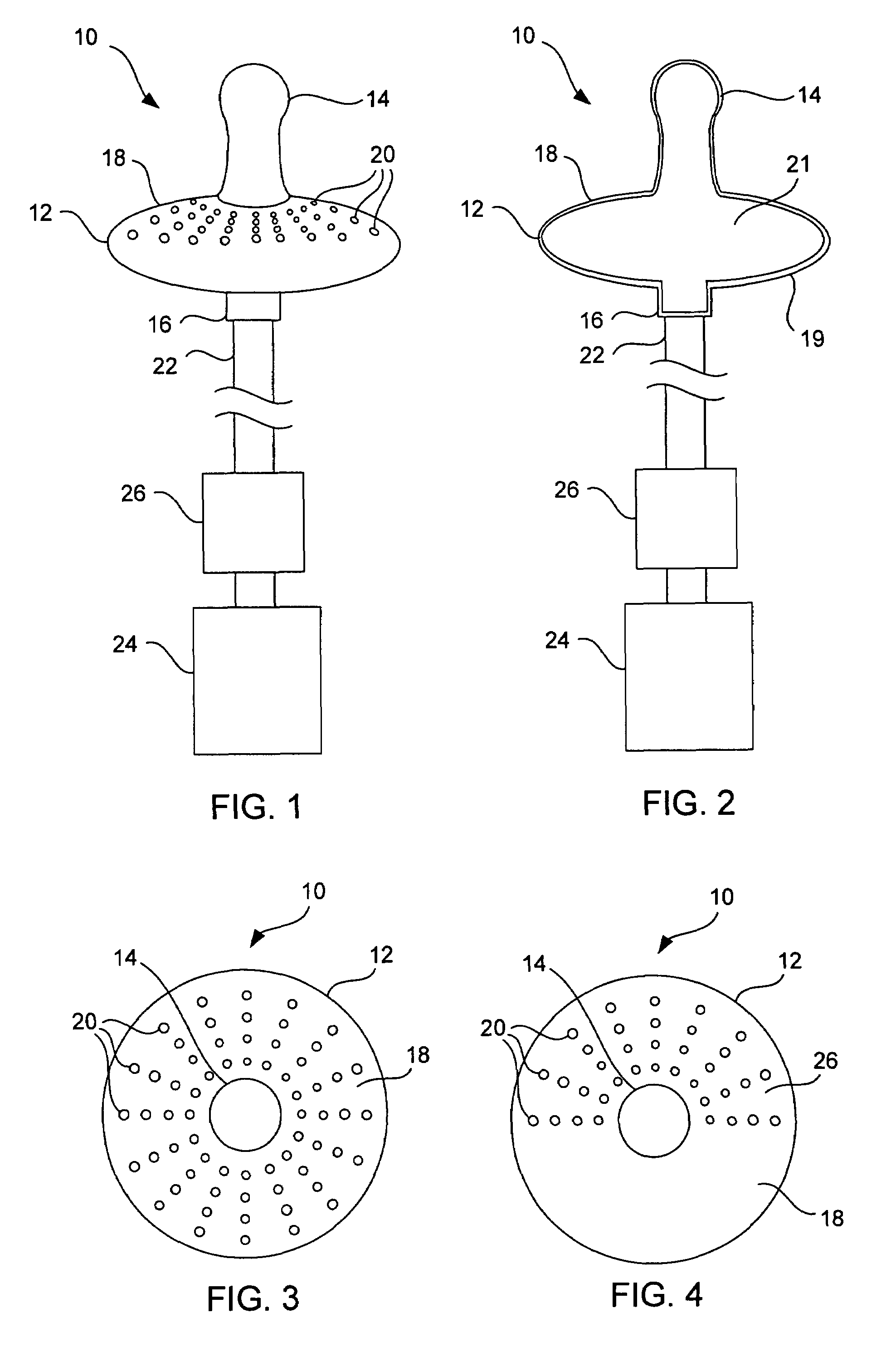
[0009]In another detailed embodiment of the present invention, the gas supply chamber can be formed of a front portion and a rear portion which are coupled together to form the gas supply chamber. Preferably, the gas supply chamber is permanently enclosed such that the hollow region is not accessible. This is particularly important in reducing the complexity of the device and manufacturing steps required. Further, as the device can be designed as a single-use item, cleaning and maintenance is not required and is preferably avoided.
[0012]In yet another aspect of the present invention, the gas delivery device can be conveniently configured as a single-use item. This helps to reduce or eliminate the amount of time and effort required to clean and / or maintain the device from patient-to-patient. Rather, the simple use and low-cost manufacturing can allow medical care providers to dispose of the device after a single use or after a specific patient. This is often not an option with other similar devices which are more expensive and complex.
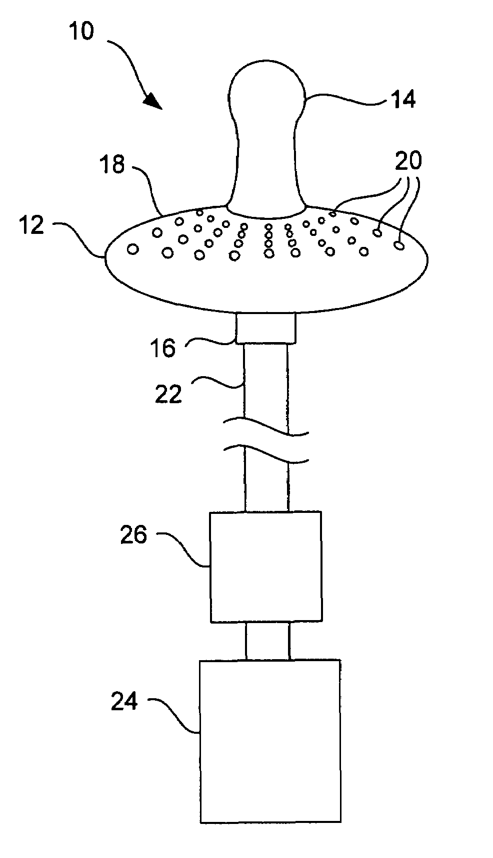
[0016]In an additional aspect of the present invention, the front portion can be configured such that the plurality of holes are substantially all directed toward the infant. In this manner, exiting gas is delivered toward the infant. Thus, in some embodiments the plurality of holes can be placed around the full face of the front portion. As a result, the position and orientation of the gas delivery device does not affect performance. Alternatively, the plurality of holes can be concentrated at an upper region of the front portion which is designed to be nearer the nose of the infant. For example, the inlet can include an elbow portion which bends downward or in an opposite direction than the upper region. Optionally, the elbow portion can be adjustable to orient the position of the upper portion closer to the nose of the infant. In any of the above embodiments, the configuration of the plurality of holes to direct gas toward the infant helps to avoid waste of the gas which can occur during administration using devices which have either peripheral openings or include deflection and baffling features.
[0017]In yet another aspect of the present invention, a gas tube can be operatively connected to the gas inlet. The gas tube can have any length which is functional. Of particular consideration is providing a nebulizer which is upstream the gas inlet. Placing the nebulizer farther upstream can allow for fewer obstructions around the infant and less intimidation of the infant during use. For example, a gas tube having a length from about 2 feet to about 10 feet can allow for increased comfort, improved access to the infant, and convenient operation of the device.

Problems solved by technology

However, in the case of infants, masks are often difficult to attach or retain on the infant.
For example, the infant will often become frightened or agitated by such a device sufficient that they may remove the mask or decrease the effective delivery of gas.
However, these devices suffer from a number of defects which reduce their commercial and / or practical value.
This can increase the weight of the device and can be an intimidating view to infants.
Further, many of these devices include holes in the sucking portion which can be problematic in controlling the rate of delivery of medicine and oxygen.
In addition, many of the available devices are relatively expensive to manufacture and can be difficult to use.

Method used


Image

  • Gas delivery device for infants
  • Gas delivery device for infants

Examples


Embodiment Construction

[0026]Reference will now be made to exemplary embodiments and specific language will be used herein to describe the same. It will nevertheless be understood that no limitation of the scope of the invention is thereby intended. Alterations and further modifications of the inventive features, process steps, and materials illustrated herein, and additional applications of the principles of the inventions as illustrated herein, which would occur to one skilled in the relevant art and having possession of this disclosure, are to be considered within the scope of the invention. It should also be understood that terminology employed herein is used for the purpose of describing particular embodiments only and is not intended to be limiting.

[0027]A. Definitions

[0028]In describing and claiming the present invention, the following terminology will be used.

[0029]The singular forms “a,”“an,” and “the” include plural referents unless the context clearly dictates otherwise. Thus, for example, refe...


PUM


Abstract

An improved gas delivery device for infants which is simple and easy to use is disclosed and described. The gas delivery device can include a gas supply chamber and a nipple directly connected to the supply chamber. The gas supply chamber can define a substantially hollow region and can have a front portion which has the nipple connected thereto. The front portion has a plurality of holes which are designed to direct gas forward from the hollow region toward the infant. The nipple can be a substantially continuous material. Such a gas delivery device is unobtrusive, easy to use, and inexpensive to manufacture.

Description

RELATED APPLICATIONS[0001]This application claims the priority of U.S. Provisional Application No. 60 / 543,093, filed Feb. 9, 2004, which is incorporated herein by reference in its entirety.FIELD OF THE INVENTION[0002]The present invention relates generally to medical devices used for delivery of gases. More specifically, the present invention relates to medical devices used for delivery of gases, such as oxygen, to an infant. Accordingly, the present invention involves the fields of medical devices, pediatrics, and materials science.BACKGROUND OF THE INVENTION[0003]During medical treatments it is often desirable to deliver oxygen and / or other gases to a patient. Oxygen can be used in treatment of respiratory distress, RSV, croup, bronchitis, or any number of other medical treatments. A wide variety of medical devices and processes for delivering gases to a patient are available. The most common device is an oxygen mask which can be held or strapped to the head of a patient. However,...

Claims


Application Information

Patent Timeline
Patent Type & Authority Patents(United States)
IPC IPC(8): A61M16/00A61J17/00A62B18/08A61M16/04A61M16/06A61M16/10
CPCA61J17/00A61M16/06A61M16/10A61M16/0493A61J2017/006A61M2202/02A61M2202/0208A61M2210/0625A61J7/0053A61J17/001
Inventor COCKERHAM, DANIEL S.
Owner COCKERHAM DANIEL S
Why Eureka
Try Eureka