Check patentability & draft patents in minutes with Patsnap Eureka AI!

Delay generator with symmetric signal paths

a delay generator and signal path technology, applied in the field of electronic circuits, can solve problems such as severe limits on the performance of the system

Inactive Publication Date: 2008-01-15
AVAGO TECH INT SALES PTE LTD
View PDF15 Cites 8 Cited by
  • Summary
  • Abstract
  • Description
  • Claims
  • Application Information

AI Technical Summary

Benefits of technology

The proposed solution effectively controls the timing of signals, ensuring accurate processing even at high frequencies by adjusting the delay elements to maintain precise phase relationships, thereby enhancing the performance of electronic systems.

Problems solved by technology

As the operating frequencies of electronic circuits continue to increase, the timing relationships between signals can severely limit the performance of the system.
For example, if a clock signal triggers the execution of a function requiring two digital input signals, the function will produce an erroneous result if the clock signal triggers the function before one or both of the digital inputs are available.

Method used


Image

  • Delay generator with symmetric signal paths
  • Delay generator with symmetric signal paths
  • Delay generator with symmetric signal paths

Examples


Embodiment Construction

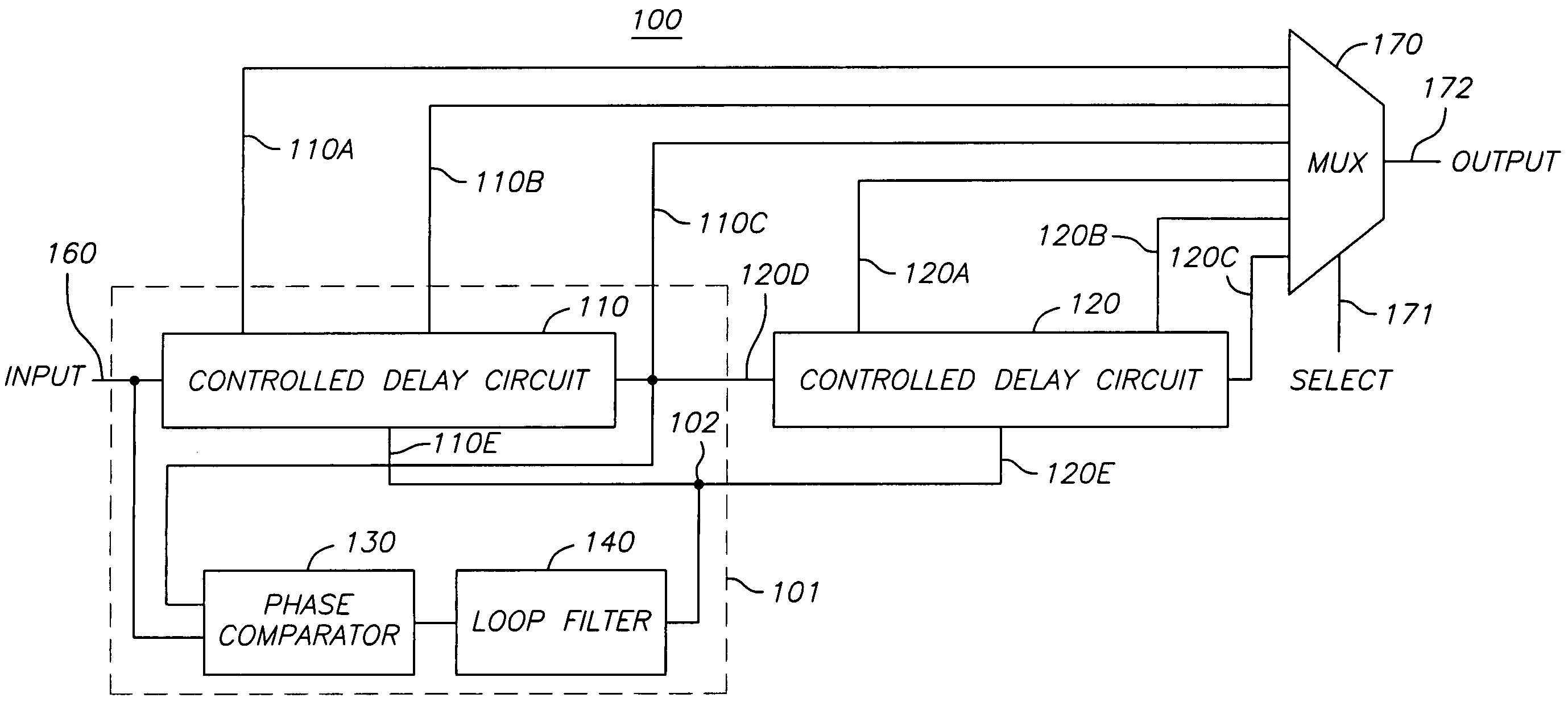
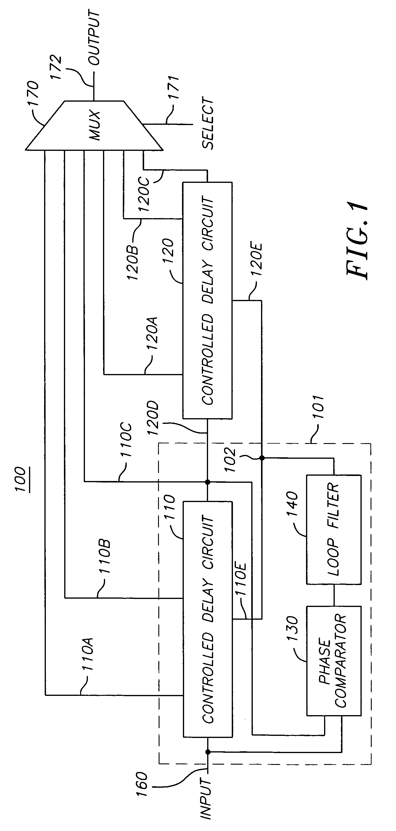
[0023]FIG. 1 illustrates a delay circuit 100 according to one embodiment of the present invention. Delay circuit 100 may be used to generate delayed signals useful for a variety of application in an electronic system or integrated circuit. Delay circuit 100 includes a delay locked loop 101 and controlled delay circuit 120. Delay locked loop 101 includes an input terminal 160 for receiving a periodic input signal. Delay locked loop 101 includes circuitry for generating a delayed periodic signal, or signals, such as delayed signals on output terminals 110A-110C for example. Delayed signals are also sometimes referred to as skewed signals. Delay locked loop 101 also generates a control signal 102 for controlling the time delay between the periodic input signal received at input terminal 160 and the delayed periodic signal or signals.

[0024]Delay circuit 100 also includes a controlled delay circuit 120. Controlled delay circuit 120 generates an additional delayed periodic signal, or sign...


PUM


Abstract

A delay circuit generates delayed signals. The delay circuit includes a delay locked loop having an input terminal coupled to a periodic input signal, the delay locked ioop generating one or more delayed periodic signals and a control signal for controlling the time delay between the periodic input signal and the delayed periodic signals. The delay circuit also includes a controlled delay circuit for generating one or more delayed periodic signals. The controlled delay circuit has an input terminal for receiving at least one of the delayed periodic signals from the delay locked loop and a delay control terminal coupled to the control signal from the delay locked ioop for controlling the time delay between the delayed periodic input signal received from the delay locked loop and the one or more delayed periodic signals generated by the controlled delay circuit.

Description

CROSS-REFERENCE TO RELATED APPLICATION(S)[0001]This application is a continuation of U.S. patent application Ser. No. 10 / 243,086, filed Sep. 12, 2002, now U.S. Pat. No. 6,870,415, the disclosure of which is hereby incorporated by reference herein.BACKGROUND[0002]The present invention relates in general to electronic circuits and in particular to an electronic circuit for generating delays using a delay locked loop.[0003]The growth and maturity of the electronics industry has led to a variety of products that have changed the way people live and work. Electronic circuits are currently the dominant technology for creating products that move and shape information. In the world of electronics, information is typically represented by zeros and ones. Electronic representations of zeros and ones are referred to as digital signals. Electronic circuits process digital signals to perform a wide variety of functions.[0004]However, as the electronics industry continues to grow, there is an ever...

Claims


Application Information

Patent Timeline
Patent Type & Authority Patents(United States)
IPC IPC(8): H03L7/06H03H11/12H03H11/26
CPCH03H11/265H03H11/126
Inventor ZHANG, BOYIN, GUANGMING
Owner AVAGO TECH INT SALES PTE LTD
Features
  • R&D
  • Intellectual Property
  • Life Sciences
  • Materials
  • Tech Scout
  • Unparalleled Data Quality
  • Higher Quality Content
  • 60% Fewer Hallucinations
Learn More