Noise suppression system

a noise suppression and noise technology, applied in direction finders, instruments, acoustic wave reradiation, etc., can solve the problems of affecting the performance of mvdr algorithms, finite time to estimate the spatial coherence of the acoustic field, and the noise of all these sources can be very loud, so as to achieve the effect of suppressing the nois

Inactive Publication Date: 2008-01-15
UNITED STATES OF AMERICA +1
View PDF4 Cites 8 Cited by
  • Summary
  • Abstract
  • Description
  • Claims
  • Application Information

AI Technical Summary

Benefits of technology

[0012]Therefore, it is an object of the present invention to provide a sy

Problems solved by technology

Ambient noise from all these sources can be very loud, especially in coastal waters where surface ship densities are largest, and these loud noise signals can prevent the detection of weaker signals of interest.
However, there is only a finite time to estimate the acoustic field spatial coherence.
Furthermore, errors between the actual and estimated acoustic field spatial coherence degrade the performance of MVDR algorithms rapidly because MVDR algorithms are highly non-linear.
Small errors in the estimate of CSM can propagate to become very large errors in the estimate of the inverse matrix of CSM.
Therefore, MVDR algorithms are not robust in realistic open ocean environments, and are severely degraded when short averagin

Method used


Image

  • Noise suppression system
  • Noise suppression system
  • Noise suppression system

Examples


Embodiment Construction

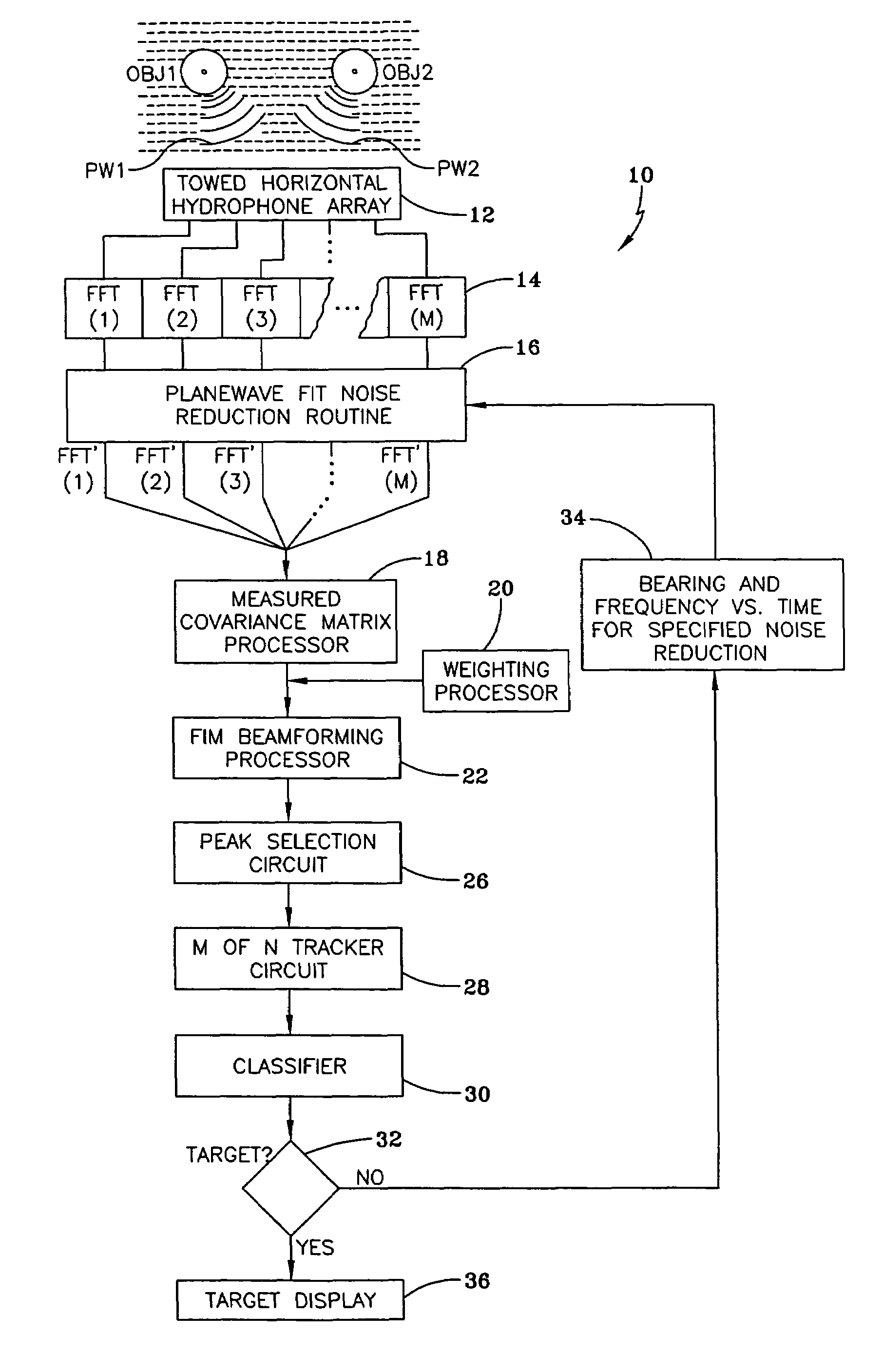
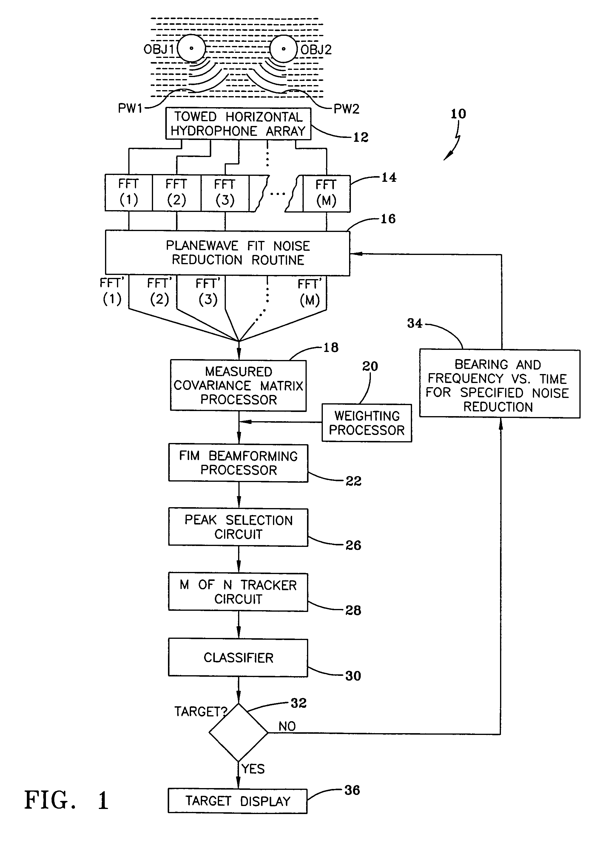
[0019]The present invention is an extension of the invention described in U.S. Pat. No. 5,481,505, which is herein incorporated by reference. The present invention utilizes tracker inputs from the “Eight Nearest Neighbor Peak Picker (ENNPP)” which is completely described in U.S. Patent 5,481,505. For the sake of brevity, the details of the operation of the system of U.S. Pat. No. 5,481,505, although applicable to the present invention, are not repeated herein, but rather are referenced as needed. While the current invention was conceived as an improvement to U.S. Pat. No. 5,481,505, it should be evident that it is applicable to any system providing bearing and azimuth inputs to the algorithm.

[0020]In general, the technique of the present invention determines the phases and amplitudes of the noise sources to be suppressed by modeling the noise sources as planewave time series whose amplitudes and phases are determined from the measured time series input and the bearing-time and frequ...


PUM


Abstract

A method and apparatus is provided for suppressing noise which includes receiving a plurality of signals from an array of sensors and transforming each of these signals to the frequency domain. The transformed signals are beamformed so that noise sources can be identified by bearing and frequency range. A planewave-fit noise-suppression routine is then used to remove identified noise sources from the transformed signals and to provide a noise-suppressed transformed signal having signals from said identified noise sources suppressed.

Description

STATEMENT OF GOVERNMENT INTEREST[0001]The invention described herein may be manufactured and used by or for the Government of the United States of America for Governmental purposes without the payment of any royalties thereon or therefore.BACKGROUND OF THE INVENTION[0002](1) Field of the Invention[0003]The present invention generally relates to sonar systems and more specifically to sonar systems particularly adapted for identifying the location of an underwater object(s).[0004](2) Description of the Prior Art[0005]Conventional passive sonar systems detect acoustic signals emanating from an underwater object; that is, any device that moves through the water while emitting acoustic signals that sonar can detect. Torpedoes and submarines are examples of such underwater objects.[0006]As modern, very quiet submarine platforms become operational in large numbers, new methods of detecting very low level signals from these quiet submarine platforms are desired, especially in the presence o...

Claims


Application Information

Patent Timeline
IPC IPC(8): G01S3/86
CPCG01S3/86G01S5/18Y10S367/901
Inventor DONALD, JAMES B.NUTTALL, ALBERT H.WILSON, JAMES H.
Owner UNITED STATES OF AMERICA
Why Eureka
Try Eureka