Method of processing an acoustic signal, and a hearing instrument

a processing method and acoustic signal technology, applied in the direction of transducer casings/cabinets/supports, electrical transducers, electrical apparatus, etc., can solve the problems of affecting the use of hearing instruments, and requiring far too long delays for hearing instruments (hi). , the effect of computational efficiency

Active Publication Date: 2008-01-15
SONOVA AG
View PDF15 Cites 5 Cited by
  • Summary
  • Abstract
  • Description
  • Claims
  • Application Information

AI Technical Summary

Benefits of technology

[0019]It is an object of this invention to provide a method and a device for suppressing reverberation, which method is robust, is computationally not expensive, and avoids drawbacks of corresponding prior art methods. More concretely, it is an object of the invention to provide a method of obtaining an output signal from an acoustic input signal, which method causes reverberation contributions to the acoustic input signal to be suppressed in the output signal. The method should be computationally inexpensive, robust and should overcome drawbacks of according prior art methods.
[0033]A measure of the signal evaluation may be obtained by calculating the difference between the converted signal input power and the converted signal input power delayed by a delay T. Then, the room impulse attenuation value may be chosen to be the maximum attenuation during a time span corresponding to T, as observed during a much larger time period I. In other words, the room impulse attenuation value RIatt used is the maximum negative slope multiplied by T. (The negative slope itself is not required and does not have to be calculated, though). Several maximum values during the time period I may get averaged to increase robustness.
[0037]The method according to the invention, although its basic principle is comparable to the one of prior art methods, is surprisingly simple and computationally significantly cheaper. It makes use of quantities often already available in a hearing instrument, such as logarithmic signal power etc. Compared to the above described prior art method by K. Lebart et al., it avoids the explicit complex and computationally expensive estimation of the reverberation time Tr in order to generate the exponential term in eq. (2) for the reverberation power estimation.
[0038]Next to providing a far simpler solution for the estimation of the reverberation time Tr, or a measure for it, respectively, it also allows to implement a simpler gain rule. Therefore, it is computationally efficient. Computational efficiency is still of prime importance in hearing instruments. By also eliminating the error-prone step of speech pause detection, robustness is improved as well.

Problems solved by technology

Reverberation is a major problem for hearing impaired persons.
Thus, severe intelligibility reductions as well as comfort decreases occur.
), even when only the first part of the RIR (the one with the highest energies) gets corrected for, far too long delays for hearing instrument (HI) purposes would be required.
), which is considered a hard problem in the field to solve, and no completely satisfying and useful solutions exist.
This, however, is of limited use in large rooms, where the sound field is very diffuse.
These solutions are computationally not cheap either, and also require a significant group delay.
Also, they are not very robust.
An algorithm based on these findings is of lower complexity than above mentioned direct dereverberation or cepstral methods, but is still computational expensive.
(2) for the reverberation power estimation, is hard to calculate: First, speech pauses are detected (which is rather difficult in a highly reverberated signal).
Then, within these signal segments the slope of the smoothed signal power envelope on a dB scale is extracted by linear regression, another quite expensive operation.
Next to being computationally expensive, the above described method also lacks a certain amount of robustness.
This is, among other reasons, due to uncertainties in detecting speech pauses.

Method used


Image

  • Method of processing an acoustic signal, and a hearing instrument
  • Method of processing an acoustic signal, and a hearing instrument
  • Method of processing an acoustic signal, and a hearing instrument

Examples


Embodiment Construction

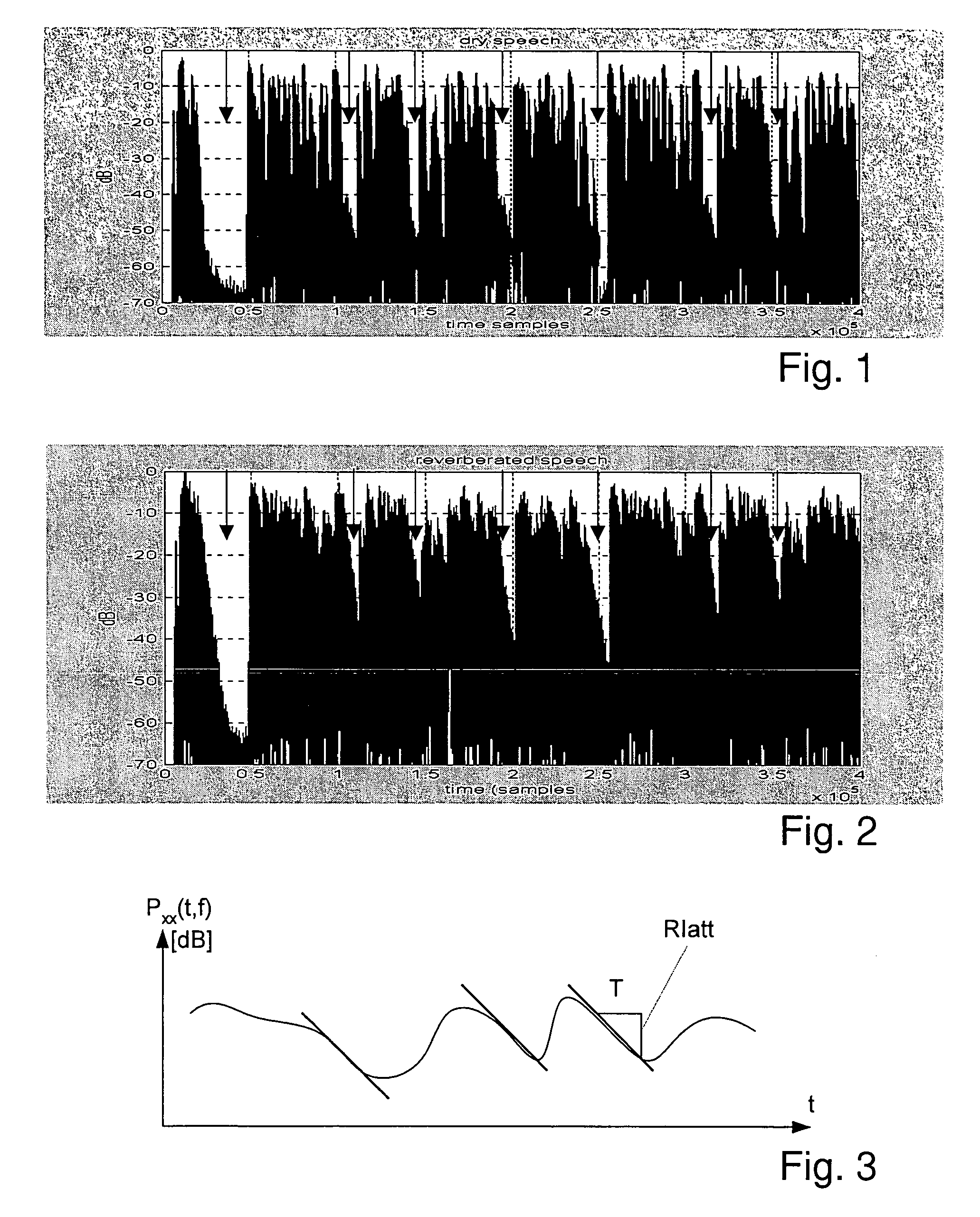
[0050]FIG. 1 depicts, on a logarithmic scale, the signal power of a dry (not reverberated) speech signal as a function of time, showing the nonlinear negative slopes in the speech pauses. In the figure, the speech pauses are pointed out by arrows.

[0051]FIG. 2 shows the corresponding plot of approximately the same speech signal, which however is reverberated. In the speech pauses, the approximately linear negative slopes may be seen. For hearing instrument users, the blurring of speech pauses by reverberation may decrease speech intelligibility.

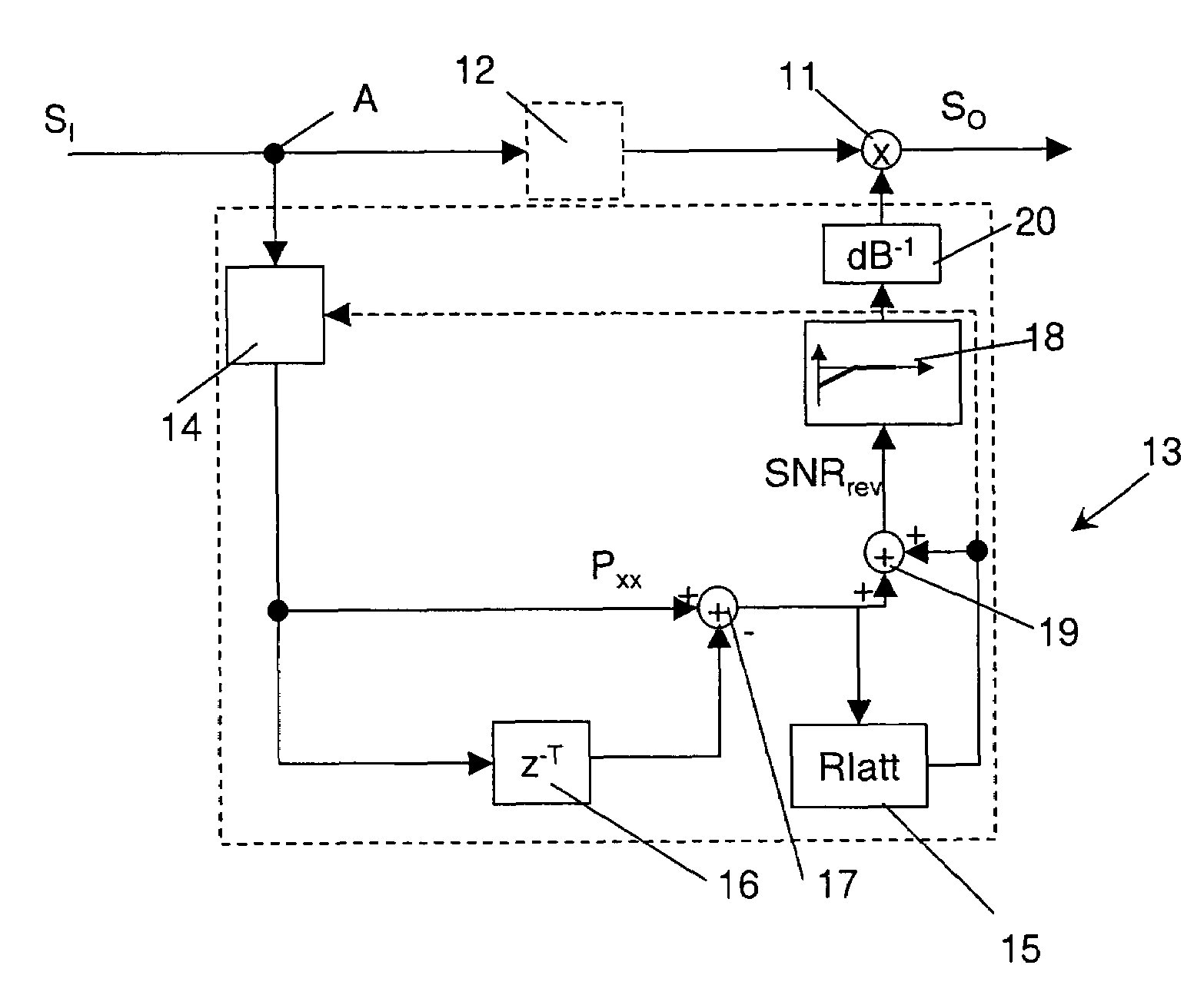
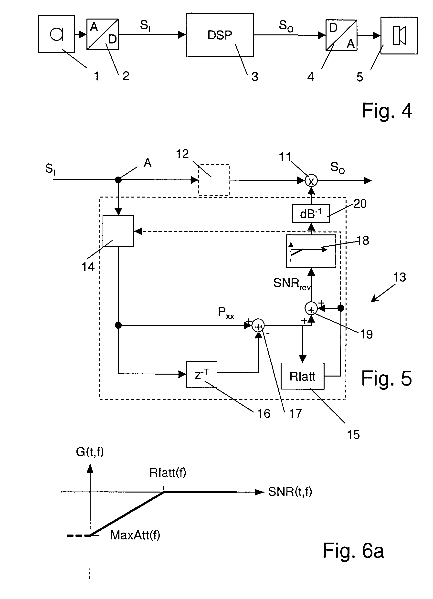
[0052]An important finding of the invention is, that the maximal negative slope found over such a (properly pre-processed) signal envelope is a good indicator of the reverberation time Tr. In other words, even for immediate drops in the (speech) signal, the reverberated signal will never decay faster than given by Tr. FIG. 3 shows this relation. The power Pxx of a reverberated speech signal in a frequency band f (here, f is a discrete variable...


PUM


Abstract

A method of processing an acoustic input signal into an output signal in a hearing instrument includes converting the acoustic input signal into a converted input signal, and applying a gain to the converted input signal to obtain the output signal. According to the invention, the gain is calculated using a room impulse attenuation value being a measure of a maximum negative slope of the a converted input signal power on a logarithmic scale. The calculation of the gain may include evaluating a signal power development value being a measure of the actual converted input signal power attenuation or signal power increase, evaluating a signal-to-reverberation-noise ratio from the signal power development value and the room impulse attenuation value, and calculating, based on a gain rule, said gain from said signal-to-reverberation-noise ratio.

Description

FIELD OF THE INVENTION[0001]This invention is in the field of processing signals in or for hearing instruments. It more particularly relates to a method of converting an acoustic input signal into an output signal, a hearing instrument, and to a method of manufacturing a hearing instrument.BACKGROUND OF THE INVENTION[0002]Reverberation is a major problem for hearing impaired persons. The reason is that, in addition to the missing spectral cues for speech intelligibility from the broadening of the auditory filters (i.e. the reduced spectral discrimination ability of the impaired ear, due to defect outer hair cells, resulting in less sharply tuned auditory filters in the impaired ear), the temporal cues also are mitigated by the reverberation. Onsets, speech pauses etc. are no longer perceivable. Thus, severe intelligibility reductions as well as comfort decreases occur.[0003]From a technical point of view, reverberation is a filtering (convolution) of the clean signal, for example a ...

Claims


Application Information

Patent Timeline
Patent Type & Authority Patents(United States)
IPC IPC(8): H04R25/00H04B1/00
CPCH04R25/453H04R2225/43H04R25/505
Inventor ROECK, HANS-UELIFEILNER, MANUELA
Owner SONOVA AG
Why Eureka
Try Eureka